Transmission line ice coating clearing device

A technology for transmission lines and removal devices, applied in the installation of cables, overhead lines/cable equipment, electrical components, etc., can solve the problems of increasing the quality of transmission lines, inconvenient hanging and taking, avoiding damage and damage to transmission lines, and ensuring stability. Sexual, mobile and flexible effects

Active Publication Date: 2018-11-16
PINGDINGSHAN POWER SUPPLY ELECTRIC POWER OF HENAN +1
View PDF5 Cites 1 Cited by
  • Summary
  • Abstract
  • Description
  • Claims
  • Application Information

AI Technical Summary

Problems solved by technology

Although the invention has a simple structure, it still adopts the suspension method, whic

Method used


Image

  • Transmission line ice coating clearing device
  • Transmission line ice coating clearing device
  • Transmission line ice coating clearing device

Examples


Embodiment 1

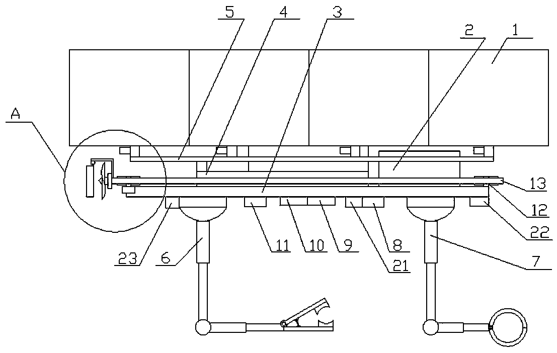
[0035] A power transmission line deicing device, comprising a deicing base 3, a suspension mechanism set on the deicing base 3, a moving mechanism set on the deicing base 3, a moving mechanism set on the deicing base 3 The auxiliary support mechanism 7 on the base 3, the deicing mechanism 6 arranged on the deicing base 3, and the suspension mechanism, the moving mechanism, the auxiliary supporting mechanism and the The control mechanism for the coordinated control of the deicing mechanism;

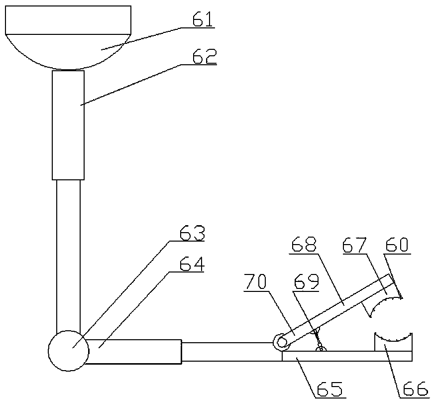
[0036] The deicing mechanism 6 includes a third two-axis platform 61 arranged on the deicing base 3, and a third auxiliary support telescopic rod 62 arranged on the third two-axis platform 61 is arranged on the The fourth two-axis platform 63 at the end of the third auxiliary support telescopic rod 62 is arranged on the fourth auxiliary support telescopic rod 64 on the fourth two-axis platform 63, and the fourth auxiliary support telescopic rod 64 is arranged on the fourth auxiliary suppor...

Embodiment 2

[0044] The difference from Embodiment 1 is that: the deicing base 3 is provided with an anti-collision metal mesh matched with the suspension airbag.

[0045] Both the upper extrusion groove and the lower extrusion groove are provided with extrusion protrusions 60 .

[0046] The anti-collision metal mesh used in this embodiment is preferably arranged on the surface of the airbag, and adopts the mode of elastic steel belt.

Embodiment 3

[0048] The difference between it and the second embodiment is that hydrogen gas is set in the first compression tank 4 .

[0049] The compressed gas used in this embodiment is hydrogen, which is less dangerous because it is in a low-temperature environment and produces better buoyancy.


PUM


Abstract

The present invention provides a power transmission ice coating clearing device. The device comprises a de-icing base, a suspension mechanism disposed on the de-icing base, a moving mechanism disposedon the de-icing base, an auxiliary supporting mechanism disposed on the de-icing base, a de-icing mechanism disposed on the de-icing base, and a control mechanism which is arranged on the de-icing base and is used for controlling the suspension mechanism, the moving mechanism, the auxiliary supporting mechanism, and the de-icing mechanism in a coordinative manner. With the power transmission icecoating clearing device of the invention adopted, the load quality of a transmission line is not increased, ice can be smoothly removed, the suspension difficulty of the device is decreased, and damage to the transmission line can be decreased.

Description

technical field [0001] The invention relates to the technical field of impurity removal equipment for power transmission lines, in particular to a power transmission line ice removal device. Background technique [0002] The icing disaster of transmission lines is one of the main factors that affect the safety of transmission lines in winter. The main reason is that a large number of ice blocks are attached to them, which leads to an increase in the quality of transmission lines. There will be a tower collapse, which will cause the paralysis of the transmission line. There are two solutions. One is to enhance the design strength of the transmission line, and the other is to de-ice in time. The existing de-icing devices are divided into hand-held , Hanging or unmanned aerial vehicles, the handheld is the most primitive, which will increase the difficulty of the operator's operation, while the hanging type will increase the quality of the transmission line, and the use of unma...

Claims


Application Information

Patent Timeline
IPC IPC(8): H02G7/16H02G1/02
CPCH02G1/02H02G7/16
Inventor 王逸超冯政协肖承仟郭毅鹏孙世勇周春雷韩一霈刘智强
Owner PINGDINGSHAN POWER SUPPLY ELECTRIC POWER OF HENAN
Why Eureka
Try Eureka