
DC micro-grid system and charging loop circuit and control method thereof

A charging circuit and circuit technology, applied in the field of circuits, can solve problems such as waste of resources, achieve the effects of saving costs, optimizing PCB layout and wiring, and reducing the number of components

Active Publication Date: 2018-11-16
GREE ELECTRIC APPLIANCES INC
View PDF4 Cites 4 Cited by
  • Summary
  • Abstract
  • Description
  • Claims
  • Application Information

AI Technical Summary

Problems solved by technology

[0008] The present invention provides a DC micro-grid system, a charging loop circuit and a control method thereof, so as to at least solve the problem of waste of resources caused by charging loops on both the high-voltage side and the low-voltage side of a bidirectional DC / DC converter in the related art

Method used


Image

  • DC micro-grid system and charging loop circuit and control method thereof
  • DC micro-grid system and charging loop circuit and control method thereof
  • DC micro-grid system and charging loop circuit and control method thereof

Examples


Embodiment Construction

[0027] The characteristics and exemplary embodiments of various aspects of the present invention will be described in detail below. In order to make the purpose, technical solutions and advantages of the present invention more clear, the present invention will be further described in detail below in conjunction with the accompanying drawings and embodiments. It should be understood that the specific embodiments described here are only used to explain the present invention, not to limit the present invention. It will be apparent to one skilled in the art that the present invention may be practiced without some of these specific details. The following description of the embodiments is only to provide a better understanding of the present invention by showing examples of the present invention.

[0028] It should be noted that in this article, relational terms such as first and second are only used to distinguish one entity or operation from another entity or operation, and do not...


PUM


Abstract

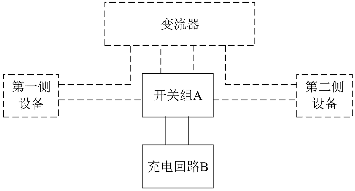
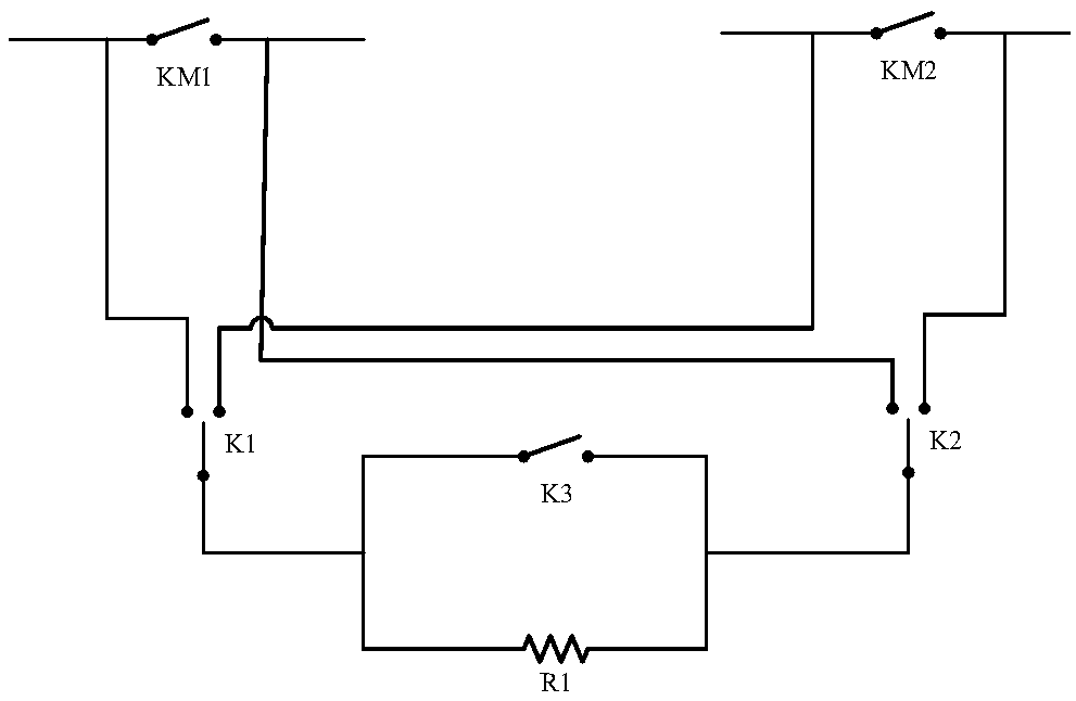
The invention provides a DC micro-grid system and a charging loop circuit and a control method thereof. The charging loop circuit enables a charging loop to be selectively connected to a first side loop or a second side loop through a switch group. The DC micro-grid system and the charging loop circuit and the control method thereof solve the problem of resource waste caused since the charging loops need to be designed on both sides of a converter, thereby reducing the device number of the charging loop, saving cost, saving space and helping to optimize PCB locating and wiring.

Description

technical field [0001] The invention relates to the field of circuits, in particular to a DC microgrid system, a charging loop circuit and a control method thereof. Background technique [0002] With the rapid development of energy storage systems in recent years, bidirectional converters in the field of new energy have also been better developed. Among them, the bidirectional DC / DC converter is widely used. In the field of distributed energy, there is a bidirectional DC / DC of the energy storage system to the DC micro-grid bus; for new energy vehicles, there are on-board bidirectional DC / DC chargers, and in other fields, there are bidirectional DC / DC digital power supplies. [0003] There is usually a charging capacitor in the bidirectional DC / DC converter. In order to avoid the impact of the current on the component when it is powered on, the current popular solution is to connect a charging circuit to its front end and back end to realize soft start. Features. Tradition...

Claims


Application Information

Patent Timeline
Patent Type & Authority Applications(China)
IPC IPC(8): H02J7/00
CPCH02J7/0068H02M1/36H02J7/345H02M3/04H02J7/007182H02J7/00714H02J7/0029
Inventor 蒋世用张祥冯重阳陈宁宁李萌张羽
Owner GREE ELECTRIC APPLIANCES INC
Learn More