Supercharge Your Innovation With Domain-Expert AI Agents!

Pupil pen convenient for measurement

A pupil and convenient technology, applied in the field of pupil pen, can solve the problems of difficulty in controlling the circle diameter of the scale passing through the pupil, large reading error, etc., and achieve the effect of convenient measurement and reduction of errors.

Inactive Publication Date: 2018-11-20
海南医学院第二附属医院 +2
View PDF5 Cites 2 Cited by
  • Summary
  • Abstract
  • Description
  • Claims
  • Application Information

AI Technical Summary

Problems solved by technology

It is to use the pupil pen to illuminate the shadow with the scale, and judge the pupil size by reading the scale. This method needs to read the readings at both ends and then add and subtract each time. At the same time, it is difficult to control the circle diameter of the pupil passing through the scale, and the reading error is large.

Method used


Image

  • Pupil pen convenient for measurement
  • Pupil pen convenient for measurement
  • Pupil pen convenient for measurement

Examples


Embodiment 1

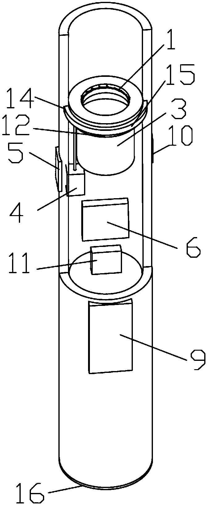
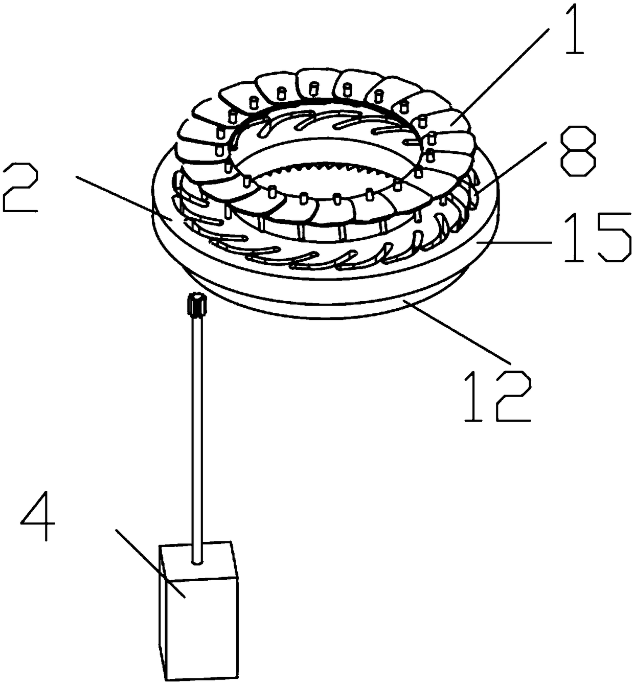
[0020] see Figures 1 to 3 , a pupil pen for convenient measurement, including several blades 1, a turntable 2, a parallel light source 3, a stepping motor 4, a motor switch 5, a display 9 and a controller 6 arranged in the pen holder, and the blade 1 can rotate to Apertures of different sizes are formed, the turntable 2 is provided with a groove 8, the blade 1 is provided with a limit block 7 sliding in the groove 8, and the turntable 2 is rotated so that it is in the groove 8 The sliding limit block 7 drives the blade 1 to rotate to form apertures of different sizes, the stepper motor 4 is used to drive the turntable 2 to rotate, and the motor switch 5 is used to control the stepper motor 4 Rotate, the parallel light source 3, the stepping motor 4, the motor switch 5, and the display 9 are respectively connected with the controller 6, and the display is arranged on the side of the pen holder.

[0021] Turntable 2 is driven by stepper motor 4, triggers motor switch 5, motor ...

Embodiment 2

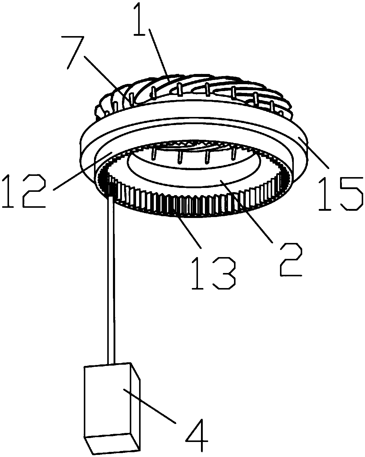
[0025] see Figures 1 to 3 The difference between this embodiment and Embodiment 1 is that the turntable 2 is provided with a drive ring 12 with an internal gear 13 , and the internal gear 13 meshes with the gear provided on the output shaft of the stepping motor 4 . The turntable 2 is provided with a drive ring 12 with an internal gear 13, and the stepper motor 4 drives the internal gear to drive the turntable 2 to rotate, which can effectively reduce the volume of the pupil pen and is easy to carry.

[0026] Specifically, an annular groove 14 is provided inside the pen holder, and a protruding ring 15 is provided on the outer edge of the turntable 2 , and the protruding ring 15 rotates in the annular groove 14 . The outer side of the turntable 2 is provided with a convex ring 15, and the convex ring 15 cooperates with the ring groove 14 to effectively limit the movement of the turntable 2 in the axial direction of the pen holder and improve the rotation stability of the turn...


PUM


Abstract

The invention discloses a pupil pen convenient for measurement. The pupil pen comprises a plurality of blades, a rotating disc, a parallel light source, a stepping motor, a motor switch, a display anda controller which are arranged in a penholder, wherein the blades can rotate to form light rings with different sizes; the rotating disc is provided with a groove; a limiting block sliding in the groove is arranged on each blade; the rotating disc is turned to ensure that the limiting block in the groove drives the blades to rotate to form the light rings with different sizes; the stepping motoris used for driving the rotating disc to rotate; the motor switch is used for controlling the stepping motor to rotate; the parallel light source, the stepping motor, the motor switch and the displayare separately connected with the controller. Light spots with the diameter being the same with that of the light rings when light passes the light sources, and are projected to pupils of a patient,the light rings are gradually reduced till being matched with the pupils of the patient, the sizes of the pupils are obtained and are displayed on the display of the outer side of the penholder, and further the sizes of the pupils are objectively and accurately judged out.

Description

technical field [0001] The invention relates to the technical field of medical equipment, in particular to a pupil pen for convenient measurement. Background technique [0002] Pupil size plays an important role in the judgment of the disease. Doctors regard the pupil as a sensitive indicator of vital functions and a major indicator in disease observation. Therefore, it is necessary to objectively record the pupil size. When a patient suffers from cerebral herniation, increased intracranial hypertension, near death, or severe brain damage, the pupil often appears dilated; when the patient suffers from atropine poisoning, cerebellar lesions, morphine poisoning, etc., the pupil often appears dilated. The judgment directly determines the accuracy of the judgment of the evolution of the patient's condition and the type of disease. At present, medical personnel often use methods to judge pupils such as: ① Subjective judgment method, which mainly relies on the work experience of ...

Claims


Application Information

Patent Timeline
IPC IPC(8): A61B3/11
CPCA61B3/112
Inventor 李珑王杰万忠琴陈擘璨李云婷林青青陈友红许艺莲钟意苗瑛铭陈玉雅鄞曼钿
Owner 海南医学院第二附属医院
Features
  • R&D
  • Intellectual Property
  • Life Sciences
  • Materials
  • Tech Scout
  • Unparalleled Data Quality
  • Higher Quality Content
  • 60% Fewer Hallucinations
Learn More