Spine traction treatment instrument
Disclosed is a technique for traction therapy and spine, which is applied to a spinal traction therapy device. It can solve the problems of aggravating physiological curvature, non-adjustable traction angle, and small adjustment range, so as to improve applicability and achieve better traction effect
- Summary
- Abstract
- Description
- Claims
- Application Information
AI Technical Summary
Problems solved by technology
Method used
Image
Examples
Embodiment 1
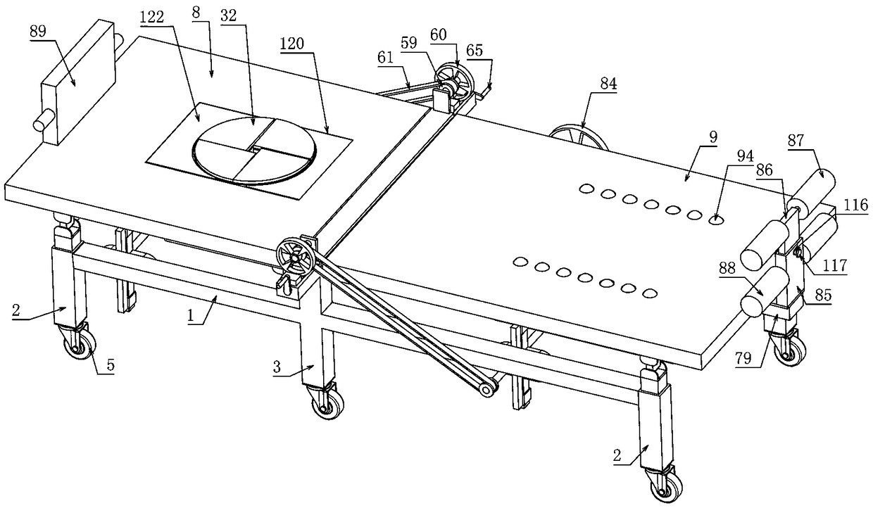
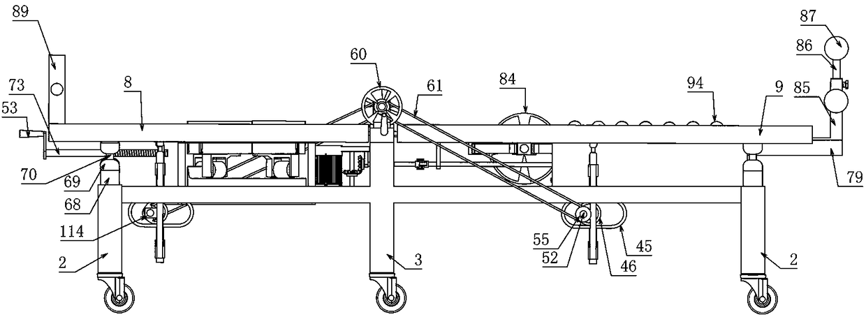
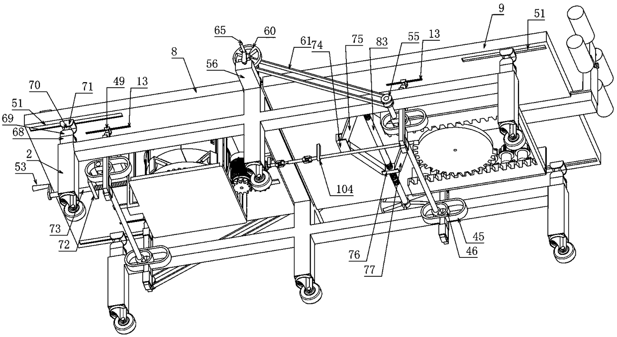
[0038] Embodiment 1, a spinal traction therapy device, includes two first rectangular rods 1 arranged longitudinally at intervals and extending laterally, the first rectangular rods 1 are provided with vertically extending first bed legs 2 on both lateral sides, and the first rectangular rods 1 The middle part is provided with a second bed leg 3 extending vertically, and a second rectangular bar 4 is connected between the upper ends of the two second bed legs 3, and it is characterized in that the lateral sides of the second rectangular bar 4 are provided with The first elongated hole 6 extending along the length direction of the second rectangular rod, and the first shaft 7 extending along the length direction of the second rectangular rod 4 is arranged between the inner longitudinal side walls of the two first elongated holes 6, The first shaft 7 on one lateral side is rotatably connected to a back support plate 8 and the first shaft 7 on the other lateral side is rotatably c...
Embodiment 2
[0040]Embodiment 2. On the basis of Embodiment 1, the traction massage device includes square thin plates 14 arranged at intervals below the back support plate 8 and parallel to the back support plate 8. The four corners of the square thin plate 8 are respectively provided with vertical To the cylindrical rod 11 that extends, the fourth convex slider 118 is connected between the top ends of the two cylindrical rods 11 on the same side in the longitudinal direction, and the lower end surface of the back support plate 8 is provided with the fourth convex slider 118 to slide Cooperating fourth convex chute 119, the square thin plate 8 is rotatably connected with the first cylinder 17 with an arc-shaped protrusion 18 on the upper end surface, and the outer wall of the first cylinder 17 placed above the square thin plate 14 A plurality of first teeth 19 are distributed in the circumferential direction, and a vertical drive motor 20 is fixed on the side of the square thin plate 14 cl...
Embodiment 3
[0042] Embodiment 3, on the basis of Embodiment 2, the traction device includes a second rectangular chute 28 placed on the upper end surface of the sector block 26 and arranged along the radial direction of the sector block 26, and the second rectangular chute 28 faces the sector block One end of the outer wall of 26 is transparent, and the end of the outer wall of the second rectangular chute 28 away from the sector block 26 is provided with a second rectangular block 29 that is slidably fitted to the second rectangular chute 28 and the upper end of the second rectangular block 29 is provided with an impervious The first rectangular hole 30 of the first rectangular hole 30 is slidably fitted with a first rectangular rod 31 and the upper end of the first rectangular rod 31 is connected with a fan-shaped sucker 32 matched with the sector block 26, and the first rectangular rod 31 The upper cover is provided with a first spring 33 and one end of the first spring 33 is connected ...
PUM
 Abstract
Description
Claims
Application Information
 - R&D
- Intellectual Property
- Life Sciences
- Materials
- Tech Scout
- Unparalleled Data Quality
- Higher Quality Content
- 60% Fewer Hallucinations
Browse by: Latest US Patents, China's latest patents, Technical Efficacy Thesaurus, Application Domain, Technology Topic, Popular Technical Reports.
© 2025 PatSnap. All rights reserved.Legal|Privacy policy|Modern Slavery Act Transparency Statement|Sitemap|About US| Contact US: help@patsnap.com


