Separating flotation device and method for micro plastics in environment soil and sediment samples

A flotation device and sediment technology are applied in the research field of pretreatment of environmental pollutants, which can solve the problems of long time and complicated operation, and achieve the effects of simple operation, low cost and wide application range.

Pending Publication Date: 2018-11-20
NANKAI UNIV
View PDF5 Cites 25 Cited by
  • Summary
  • Abstract
  • Description
  • Claims
  • Application Information

AI Technical Summary

Problems solved by technology

Before 2012, the flotation of microplastics in environmental samples mostly used traditional manual sieving and flotation methods (Hidalgo-Ruz, V. et al., Microplastics in the Marine Environment: A Review of the Methods Used for Identification and Quantification. Environmental Science &Technology, 2012, 3060-3075.), some slightly improved microplastic flotation methods have appeared in recent years, such as the "two-step method" proposed by Nuelle in Germany to extract microplastic particles in sediment samples (Nuelle, M. etc., A New Analytical Approach for Monitoring Microplastics in Marine Sediments.Environmental Pollution, 2013,161-169.), etc., but these methods have disadvantages such as cumbersome operation and long time-consuming

Method used


Image

  • Separating flotation device and method for micro plastics in environment soil and sediment samples

Examples


Embodiment 1

[0024] A separation and flotation device for microplastics in environmental soil and sediment samples, including a separation reactor part (1) and a filter part (2), wherein

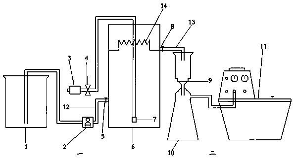
[0025]The separation reactor part (1) includes: columnar reaction body 6, air pump 3, gas flow meter 4, aeration head 7, water outlet valve 8, water outlet pipe 13, water inlet valve 5, water inlet pipe 12, peristaltic pump 2, storage The liquid cup 1; the water outlet valve 8 and the water inlet valve 5 are located on the side wall of the columnar reaction body 6, the aeration head 7 is placed at the bottom of the columnar reaction body 6, and the gas flow meter 4 is located between the air pump 3 and the aeration head 7 On the connected pipeline, one end of the peristaltic pump 2 is connected to the water inlet valve (5) through the water inlet pipe 12, and the other end is inserted below the liquid level of the liquid storage cup to pump the flotation liquid in the liquid storage cup into the columnar ...

Embodiment 2

[0028] The invention utilizes aeration and overflow methods to separate and float microplastic particles in soil or sediment samples and designs a corresponding separation and floatation device. The specific operation is as follows:

[0029] A separation and flotation device for microplastics in environmental soil and sediment samples, including a separation reactor part and a filter part, wherein the separation reactor part includes a columnar reaction body, an air pump, a gas flow meter, an aeration head, a water outlet valve, Outlet pipe, water inlet valve, water inlet pipe, peristaltic pump, liquid storage cup, filter part includes filter membrane, recovery bottle and vacuum filtration pump. Both the water outlet valve and the water inlet valve are located on the side wall of the columnar reaction body; the aeration head is placed at the bottom of the columnar reaction body; the gas flow meter is located on the pipeline connected between the air pump and the aeration head;...

Embodiment 3

[0034] A separation and flotation method for microplastics in environmental soil and sediment samples, using aeration and overflow methods to separate and float microplastic particles in soil or sediment samples. First, the water outlet valve is closed, pour the required flotation liquid into the columnar reaction body, turn on the air pump, adjust the gas flow meter, and feed a constant gas, and the gas is dispersed into small bubbles and released to the buoyant tank through the aerator head. In the liquid selection; then, slowly pour the sample from the top of the columnar reaction body, after all the samples are poured in, continue to aerate for a certain period of time, start the peristaltic pump, pump a part of the solution in the liquid storage cup into the columnar reaction body, and start Open the water outlet valve at the same time as the peristaltic pump, the upper flotation liquid carries the low-density substances through the overflow structure, flows out from the o...


PUM

PropertyMeasurementUnit
pore sizeaaaaaaaaaa
densityaaaaaaaaaa
densityaaaaaaaaaa

Abstract

The invention belongs to the field of pretreatment study of environmental pollutants and relates to a separating flotation device and method for micro plastics, in particular to separating flotation of micro plastic particles in the environment soil and sediment samples. The device comprises a separation reactor and a filter, and the micro plastic particles in the soil and sediment samples are subjected to separating flotation with aeration and overflow methods. The device is simple, simple and convenient to operate, low in time consumption and efficient, and defects of tedious operation and high time consumption of a traditional micro plastic separating flotation method are overcome. Besides, a separating flotation solution is efficient, economical and recyclable, and environmental pollution is reduced while cost is saved.

Description

technical field [0001] The invention belongs to the research field of pretreatment of environmental pollutants, and relates to a separation and flotation device and method for microplastics, in particular to the separation and flotation of microplastic particles in environmental soil and sediment samples. Background technique [0002] The term microplastics was first proposed by Thompson in the United Kingdom in 2004, when it was used to describe plastic particles smaller than 50 microns (Thompson, R. C. et al., Lost at Sea: Where is All the Plastic Science, 2004, 304, 838.). In 2009, at the International Symposium on the Emergence, Impact and Fate of Plastic Marine Litter, Arthur proposed that "microplastics" should include all particles smaller than 5 mm. So far, there is no clear definition of the size of "microplastics". Most people generally agree that they are plastic particles with a particle size of less than 5 mm, but from an intuitive point of view, the definition ...

Claims


Application Information

Patent Timeline
Patent Type & Authority Applications(China)
IPC IPC(8): B03D1/14G01N1/28
CPCG01N1/28B03D1/14
Inventor 卢学强韩晓昕
Owner NANKAI UNIV
Why Eureka
Try Eureka