Mechanical mold with convenient cooling demolding function

A mold and mechanical technology, which is applied in the field of mechanical molds that are easy to cool and demould, can solve the problems of inconvenient movement of the pressing plate, and achieve the effects of simple structure, convenient use, and easy movement

Inactive Publication Date: 2018-11-20
柳州市钜嘉机械有限公司
View PDF5 Cites 6 Cited by
  • Summary
  • Abstract
  • Description
  • Claims
  • Application Information

AI Technical Summary

Problems solved by technology

[0002] A mechanical mold is a tool used to shape objects. This tool is composed of various parts. Different molds are composed of different parts. After retrieval, the patent document with the authorized announcement number CN207222867U discloses a mechanical mold that is convenient for cooling and demoulding. , the wall and bottom of the mold shell are provided with a water cavity layer, the left end of the water cavity is provided with a water inlet, the right side of the water cavity is a water outlet, the lower end of the mold shell is provided with a cavity, and the left and right sides of the cavity are provided with Convex edge, the mold is set inside the mold shell, the mold is provided with a push plate, the push plate is surrounded by a sealing ring, the lower end of the sealing ring is provided with an array of upper sealing teeth, and the mold at the lower end of the push plate is provided with grooves. The joint between the groove and the sealing ring is provided with a lower sealing tooth that matches the upper sealing tooth. The lower end of the groove is connected to the through pipe, and the lower end of the push plate is fixed with a push rod. The diameter of the push rod is set smaller than that of the push plate. The lower end of the push rod is fixed with a pressure plate, and a limit spring is set between the pressure plate and the mold shell. High sealing performance, but this design still has shortcomings, and there is a problem that it is not convenient to move the pressing plate, so we propose a mechanical mold that is easy to cool and demould to solve the above problems

Method used


Image

  • Mechanical mold with convenient cooling demolding function
  • Mechanical mold with convenient cooling demolding function
  • Mechanical mold with convenient cooling demolding function

Examples


Embodiment Construction

[0020] The following will clearly and completely describe the technical solutions in the embodiments of the present invention with reference to the accompanying drawings in the embodiments of the present invention. Obviously, the described embodiments are only some, not all, embodiments of the present invention.

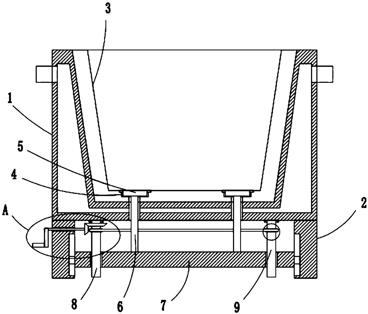
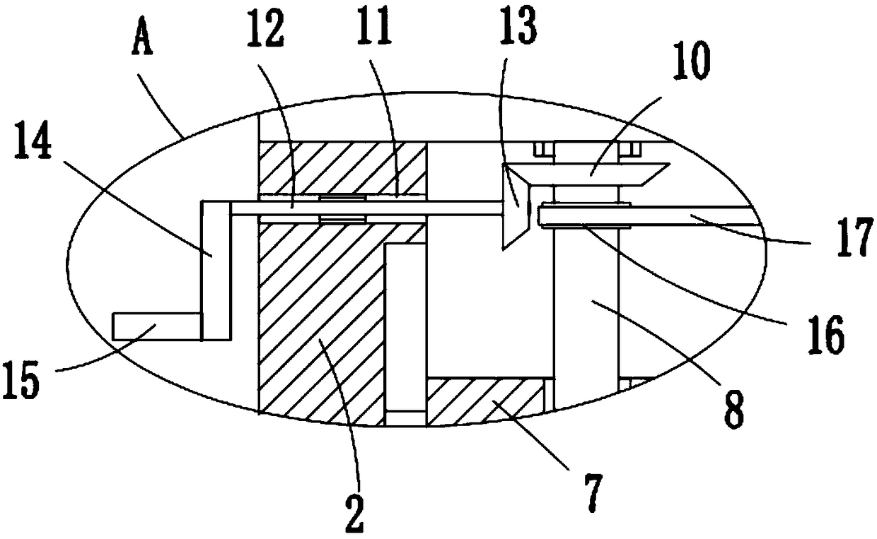
[0021] refer to Figure 1-4 , a mechanical mold that is convenient for cooling and demoulding, including a mold shell 1, two symmetrically arranged support plates 2 are fixedly installed on the bottom of the mold shell 1, a mold body 3 is arranged inside the mold shell 1, and the bottom inner wall of the mold body 3 A plurality of first grooves 4 are provided, and a push plate 5 is arranged in the first groove 4, and the push plate 5 is adapted to the first groove 4, and a push rod 6 is fixedly installed on the bottom of the push plate 5, and a plurality of The bottom ends of the push rods 6 all extend to the bottom of the mold shell 1 and are fixedly installed with ...


PUM


Abstract

The invention discloses a mechanical mold with a convenient cooling demolding function. The mechanical mold comprises a mold shell. Two symmetrically-arranged supporting plates are fixedly mounted atthe bottom of the mold shell, and a mold body is arranged in the mold shell. A plurality of first grooves are formed in the inner wall of the bottom of the mold body, and pushing plates are arranged in the first grooves and adapt to the first grooves. Pushing rods are fixedly mounted at the bottoms of the pushing plates, the bottom ends of the multiple pushing rods extend to the position below themold shell and are fixedly provided with the same pressing plate, and the two sides of the pressing plate are slidably mounted on the two supporting plates correspondingly. A first lead screw and a second lead screw are rotationally mounted at the bottom of the mold shell and are mounted on the same pressing plate in a threaded mode. The first lead screw is fixedly sleeved with a first bevel gearand a first chain wheel. According to the mechanical mold, the pressing plate can be moved conveniently, the structure is simple, and using is convenient.

Description

technical field [0001] The invention relates to the technical field of mechanical molds, in particular to a mechanical mold that is convenient for cooling and demoulding. Background technique [0002] A mechanical mold is a tool used to shape objects. This tool is composed of various parts. Different molds are composed of different parts. After retrieval, the patent document with the authorized announcement number CN207222867U discloses a mechanical mold that is convenient for cooling and demoulding. , the wall and bottom of the mold shell are provided with a water cavity layer, the left end of the water cavity is provided with a water inlet, the right side of the water cavity is a water outlet, the lower end of the mold shell is provided with a cavity, and the left and right sides of the cavity are provided with Convex edge, the mold is set inside the mold shell, the mold is provided with a push plate, the push plate is surrounded by a sealing ring, the lower end of the sea...

Claims


Application Information

Patent Timeline
IPC IPC(8): B22C9/06B22D29/04B29C33/44
CPCB22C9/06B22D29/04B29C33/442
Inventor 程志昌袁昌荣
Owner 柳州市钜嘉机械有限公司
Why Eureka
Try Eureka