Supercharge Your Innovation With Domain-Expert AI Agents!

Automatic welding machine for guide tube of oil level gauge of oil pan

An automatic welding machine and oil pan technology, which is applied in welding equipment, high-frequency current welding equipment, metal processing equipment, etc., can solve problems such as oil leakage, oil pan shell wall cracking, and lack of vibration reduction

Pending Publication Date: 2018-11-20
WUXI TIANLONG HIGH STRENGTH BOLT
View PDF8 Cites 0 Cited by
  • Summary
  • Abstract
  • Description
  • Claims
  • Application Information

AI Technical Summary

Problems solved by technology

The problem with this welding method is that the temperature of the flame sprayed by the flame torch is as high as thousands of degrees and the range is uncontrollable. While burning the welding ring, it also burns a piece of oil pan around the welding point red, resulting in the area The polymer material between the inner two layers of steel plates is completely melted, which burns the oil pan in the welding area, makes the shell wall of the oil pan hard and brittle, and causes stress concentration
In this way, under the high-frequency vibration of the engine, not only the vibration reduction effect cannot be achieved, but also the oil pan wall cracks and oil leakage will occur, making the engine unable to work normally.

Method used


Image

  • Automatic welding machine for guide tube of oil level gauge of oil pan
  • Automatic welding machine for guide tube of oil level gauge of oil pan
  • Automatic welding machine for guide tube of oil level gauge of oil pan

Examples


Embodiment Construction

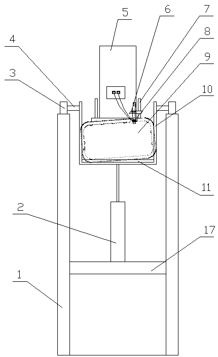
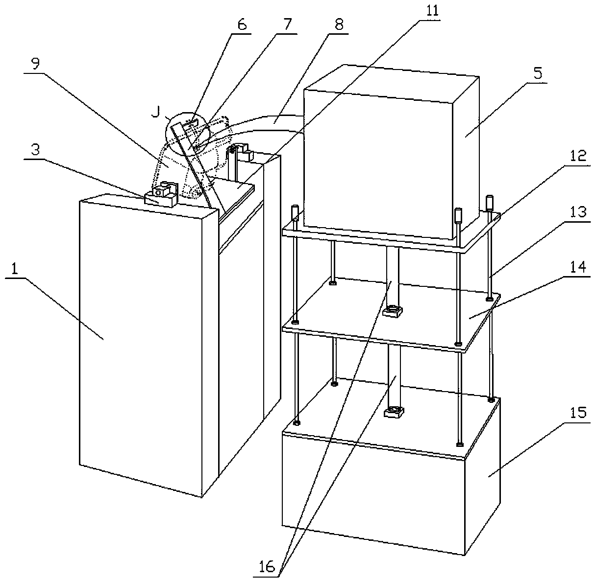
[0013] like figure 1 , figure 2 and image 3 As shown, the automatic welding machine for the oil pan oil dipstick conduit of the present invention includes a frame, and the frame includes two first columns 1 of equal height, and pin seats 3 are arranged on the upper ends of the two first columns 1 . A bracket 10 is arranged between the two pin seats 3 . Described bracket 10 is U-shaped, and pin shaft 4 is all arranged between its two ends and corresponding pin seat 3, and one end of pin shaft 4 is connected with the corresponding end of U-shaped bracket 10, and the other end of pin seat 3 is rotatable and stretches into corresponding Inside the pin seat 3, the U-shaped bracket 10 can rotate around the pin shaft 4 by an angle. The bottom of the support 10 is fixed with a support plate 11, the plate surface of the support plate is perpendicular to the two vertical arms of the U-shaped support 10. One cylinder 2. A cross brace 17 is connected between the adjacent lower ends...


PUM


Abstract

The invention relates to an automatic welding machine for a guide tube of an oil level gauge of an oil pan. The automatic welding machine is characterized by comprising a rack. Two pin seats are arranged on the upper part of the rack; a U-shaped bracket is arranged between the two pin seats; two ends of the bracket are connected to the pin seats through pin rolls; a supporting plate is arranged atthe bottom of the bracket, and a first air cylinder is arranged between the back side of the supporting plate and the bottom of the bracket. During welding, the opening of the oil pan faces forward and is connected to the bracket. A limiting rod is arranged between the back side of the supporting plate and the upper wall of the oil pan, a positioning seat is connected to the inner side of the upper end of the limiting rod, and a screw hole and a puller bolt are arranged on the positioning seat; a through hole is formed in the oil pan, a horn mouth is arranged at the outer end of the through hole, the inner end of the guide tube of the oil level gauge stretches into the horn mouth, and the front end of the puller bolt screwed through the screw hole in the positioning seat is ejected into the outer end of the guide tube of the oil level gauge. A high frequency induction heater is arranged on the back part of the rack, an electromagnetic induction coil sleeves the guide tube of the oil level gauge, and a welding ring is arranged between the electromagnetic induction ring and the horn mouth. Two ends of the electromagnetic induction coil are connected to the high frequency induction coil. By adopting the automatic welding machine provided by the invention, an engine can work normally.

Description

technical field [0001] The invention relates to a welding device. Specifically, it is an automatic welding machine used to weld the oil dipstick tube on the oil tank to the oil pan. Background technique [0002] It is known in the automobile manufacturing industry that in order to reduce the vibration noise generated by the vibration of the engine oil pan during the running of the car, most of the oil pans used on the engine are sandwich oil pans. This sandwich oil pan consists of two layers. It is composed of steel plate and polymer material between two layers of steel plate. In order to detect the oil level in the oil pan, a through hole is processed near the bottom of one side of the oil pan, and an oil dipstick conduit connected to the inner cavity of the oil pan is welded at the through hole. At present, the welding between the oil dipstick conduit and the oil pan is welded by traditional methods. This traditional method is to first fix the oil pan and the pipe with ...

Claims


Application Information

Patent Timeline
Patent Type & Authority Applications(China)
IPC IPC(8): B23K13/02
CPCB23K13/025
Inventor 卫国清
Owner WUXI TIANLONG HIGH STRENGTH BOLT
Features
  • R&D
  • Intellectual Property
  • Life Sciences
  • Materials
  • Tech Scout
  • Unparalleled Data Quality
  • Higher Quality Content
  • 60% Fewer Hallucinations
Learn More