Supercharge Your Innovation With Domain-Expert AI Agents!

Efficient and automatic welding equipment and method for light alloy motor shell

A technology for motor housings and welding equipment, applied in welding equipment, auxiliary welding equipment, welding/cutting auxiliary equipment, etc., can solve the problems of inability to weld motor housings, reducing work efficiency, and wasting labor.

Inactive Publication Date: 2021-04-27
周德伟
View PDF0 Cites 0 Cited by
  • Summary
  • Abstract
  • Description
  • Claims
  • Application Information

AI Technical Summary

Problems solved by technology

[0004] The purpose of the present invention is to provide an efficient and automatic light alloy motor shell welding equipment to solve the problem that the light alloy motor shell welding equipment in the prior art proposed in the above background technology cannot correct the motor shell when it is working. The body is fully automatic welding, the degree of automation is poor, and labor is wasted, and the welding of manpower will reduce the work efficiency over time, which will lead to the problem of low work efficiency

Method used


Image

  • Efficient and automatic welding equipment and method for light alloy motor shell
  • Efficient and automatic welding equipment and method for light alloy motor shell
  • Efficient and automatic welding equipment and method for light alloy motor shell

Examples


Embodiment 1

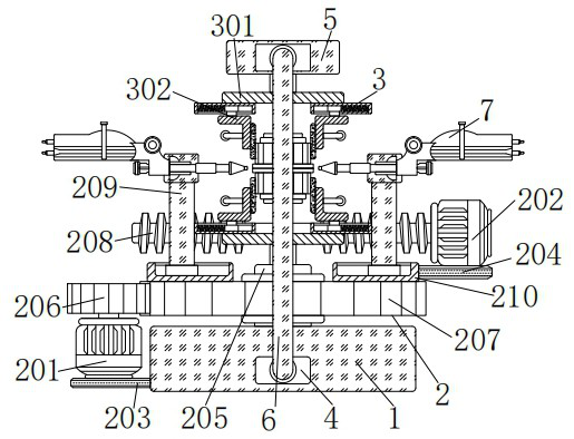
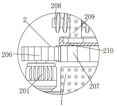
[0032] An efficient and automatic light alloy motor shell welding equipment, including a base 1, a long block 5 is arranged above the base 1, a block 4 is fixedly connected to the front end of the base 1 and the front end of the long block 5, and the block 4 The front end face is respectively fixedly connected with the upper and lower ends of the long rod 6, a welding torch 7 is provided above the base 1, and a welding device 2 is provided above the base 1, and the welding device 2 includes a first motor 201, a second motor 202, a first transverse Plate 203, second horizontal plate 204, cylinder 205, first gear 206, second gear 207, double-ended threaded rod 208, vertical plate 209, first groove plate 210 and first slide block 211, first horizontal plate 203 The right end of the base is fixedly connected to the lower left side of the base 1, the top of the first horizontal plate 203 is fixedly connected with the first motor 201, the model of the first motor 201 is ECMA-E11320RS...

Embodiment 2

[0034] As an option, see figure 1 , 4And 6, high-efficiency and automatic light alloy motor shell welding equipment, the top of the base 1 is provided with a fixing device 3, and the fixing device 3 includes a straight plate 301, a curved plate 302, a compression spring 303, a rubber pad 304, a second slider 305, The second groove plate 306 and the handle 307, the outer end of the straight plate 301 is fixedly connected with the top of the cylinder 205 and the bottom of the long block 5 respectively, the inboard of the straight plate 301 is provided with the second groove plate 306, the second groove plate 306 on the top The inner side of the top is fixedly connected with the left and right sides of the bottom of the straight plate 301 respectively, and the inner wall of the bottom groove of the second groove plate 306 is all slidably engaged with the upper outer wall of the second slider 305. Slide left and right in the groove of the slot plate 306, the upper outside of the ...

Embodiment 3

[0037] Application of highly efficient and automated light alloy motor housing welding equipment, in this embodiment, when using the highly efficient and automated light alloy motor housing welding equipment, first connect the first motor 201 and the second motor 202 to an external power supply , the compression spring 303 drives the second slider 305 to slide in the groove phase of the second groove plate (306), and then the second slider 305 drives the curved plate 302 to slide inward, and the curved plate 302 drives the rubber pad 304 to move inward , and then realize the fixing of the motor casing, avoiding the displacement of the motor casing when the motor casing is welded, which affects the welding effect, the first motor 201 starts to work, the first motor 201 drives the first gear 206 to rotate, the first The gear 206 drives the second gear 207 to rotate, and then the second gear 207 drives the first grooved plate 203 to rotate, and the second motor 202 starts working ...


PUM


Abstract

The invention discloses efficient and automatic welding equipment for a light alloy motor shell. The efficient and automatic welding equipment comprises a base, and a long block is arranged above the base; square blocks are fixedly connected to the front end face of the base and the front end face of the long block, and the front end faces of the square blocks are fixedly connected with the upper end and the lower end of a long rod separately; a welding gun is arranged above the base; and a welding device is arranged above the base. According to the efficient and automatic welding equipment for the light alloy motor shell, through cooperation of the base, the square blocks, the long block, the long rod, the welding gun and the welding device, when the equipment is used, a second gear can be driven to rotate through a first gear, and then a first groove plate is driven by the second gear to rotate; a double-end threaded rod is rotated, so that the welding gun is driven by a vertical plate to slide inwards; therefore, automatic welding of the motor shell is achieved, and the automation degree is high; and labors are saved.

Description

technical field [0001] The invention relates to the technical field of motors, in particular to an efficient and automatic light alloy motor shell welding equipment. Background technique [0002] The motor refers to an electromagnetic device that realizes the conversion or transmission of electric energy and electric energy according to the law of electromagnetic induction and electromagnetic induction. The motor is represented by the letter M in the circuit. Its main function is to generate driving torque as the power of electrical appliances or various machinery. The generator is represented by the letter G in the circuit, and its main function is to convert mechanical energy into electrical energy. In the motor production engineering, it is often necessary to weld the motor shell. [0003] The light alloy motor shell welding equipment in the prior art cannot perform fully automatic welding on the motor shell when it is working. This further leads to lower work efficiency...

Claims


Application Information

Patent Timeline
Patent Type & Authority Applications(China)
IPC IPC(8): B23K37/00B23K37/02B23K37/04B23K101/36
CPCB23K37/00B23K37/0211B23K37/0252B23K37/0443B23K2101/36
Inventor 周德伟
Owner 周德伟
Features
  • R&D
  • Intellectual Property
  • Life Sciences
  • Materials
  • Tech Scout
  • Unparalleled Data Quality
  • Higher Quality Content
  • 60% Fewer Hallucinations
Learn More