Supercharge Your Innovation With Domain-Expert AI Agents!

Automatic welding system for header welding

An automatic welding and header technology, which is applied in welding equipment, auxiliary welding equipment, welding/cutting auxiliary equipment, etc., can solve the problems of many subjective factors and heavy workload in manual operation, so as to reduce manpower, improve welding quality, reduce The effect of many subjective factors

Inactive Publication Date: 2022-04-05
郝玉国
View PDF0 Cites 0 Cited by
  • Summary
  • Abstract
  • Description
  • Claims
  • Application Information

AI Technical Summary

Problems solved by technology

[0004] The purpose of the present invention is to provide an automatic welding system for header welding, which has the advantages of no need for manual welding, turning, pushing and blanking, and solves the problems of heavy workload and many subjective factors of manual operation

Method used


Image

  • Automatic welding system for header welding
  • Automatic welding system for header welding
  • Automatic welding system for header welding

Examples


Embodiment 1

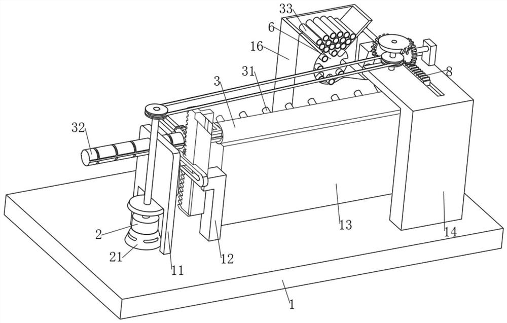
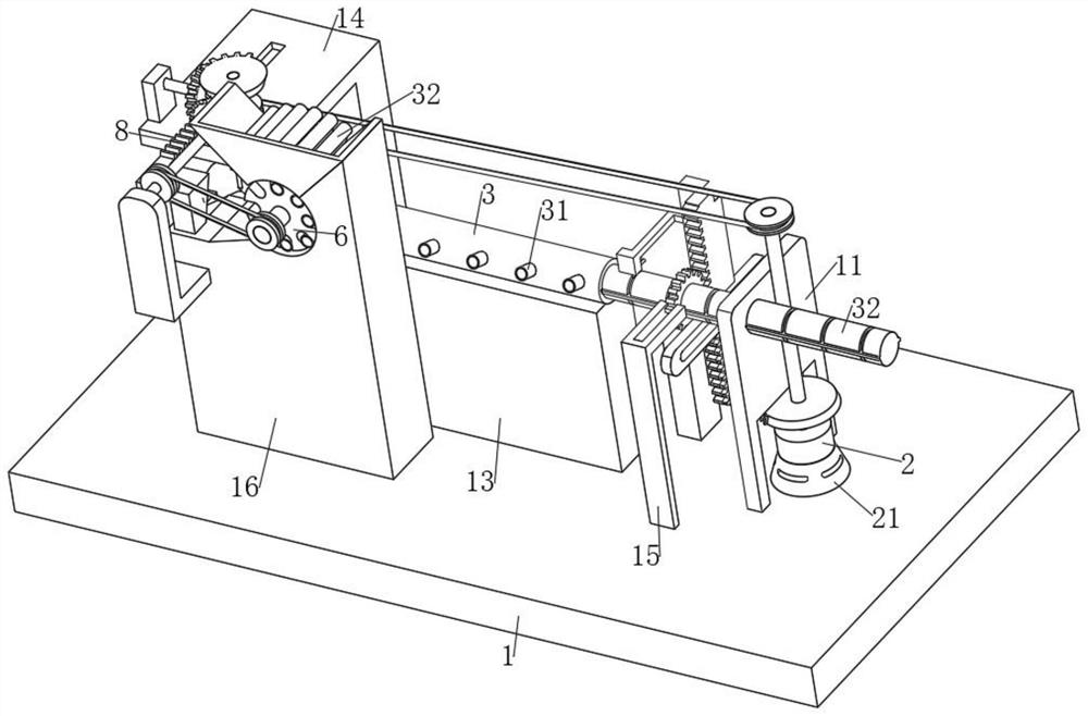
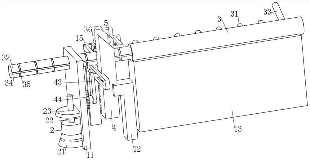
[0031] The present invention provides a technical solution: an automatic welding system for header welding, including a load-bearing plate 1 and a welding torch 7, the upper surface of the load-bearing plate 1 is fixedly connected with a first support plate 13 for supporting the total sleeve 3, the first The support plate 13 is provided with a chute for the limited sliding of the total sleeve 3, and the upper surface of the bearing plate 1 is fixedly connected with a first support frame 11, a second support plate 12 and a second support frame 14, and the first support frame 11 It is provided with a rotating mechanism for driving the total sleeve 3 to rotate so that the total sleeve and the rear half of the lower pipe can be welded. The second support plate 12 is provided with a chute and is slidably connected with the first tooth through the chute. Bar 4, the first rack 4 is provided with a pushing mechanism for pushing the total sleeve 3 so as not to be manually pushed, and th...

Embodiment 2

[0044] It is basically the same as the first embodiment, furthermore, the load-bearing plate 1 is provided with a discharge mechanism for intermittently discharging the lower-level pipe 33, the load-bearing plate 1 is fixedly connected with a support block 16, and the support block 16 is fixedly connected with a device for storing the lower-level pipe. 33 of the storage bucket 61, the fixed shaft rotation on the support block 16 is connected with a disc 6, and there are multiple sets of placement grooves for intermittently discharging the lower tube 33 on the disc 6, and the support block 16 is provided with a sliding slot for the lower tube 33. Inclined surface, the support block 16 is provided with a chute for the lower pipe 33 to be sleeved on the support sleeve 31, the disc 6 is coaxially fixedly connected with a third rotating rod 62, and the third rotating rod 62 is fixedly connected with a third rotating rod 62. Disc wheel 63.

[0045] Furthermore, the discharge mechani...

Embodiment 3

[0048] It is basically the same as the second embodiment, furthermore, the second support frame 14 is provided with a fixing mechanism for fixing the lower pipe 33 along the supporting sleeve 31 with the main sleeve 3, and the fixing mechanism includes a fixed connection on the second The third supporting plate 18 on the support frame 14, the fifth rotating rod 81 is connected with fixed axis rotation on the third supporting plate 18, and the arc profile of the fifth rotating rod 81 is fixedly connected with the second incomplete bevel gear 73 The third bevel gear 82 of intermittent meshing, the third support plate 18 is provided with a chute and is slidably connected with the second rack 8 meshing with the third bevel gear 82 through the chute limit, the second rack 8 is A fixed block 83 for fixing the lower pipe 33 along the support sleeve 31 with the main sleeve 3 is fixedly connected, a baffle 85 is fixedly connected to the lower surface of the second rack 8, and a baffle 8...


PUM


Abstract

The automatic welding system comprises a bearing plate and a welding gun, the upper surface of the bearing plate is fixedly connected with a first supporting plate used for supporting a total sleeve, and a sliding groove used for limiting sliding of the total sleeve is formed in the first supporting plate; the upper surface of the bearing plate is fixedly connected with a first supporting frame, a second supporting plate and a second supporting frame, the first supporting frame is provided with a rotating mechanism used for driving the main sleeve to rotate so that the main sleeve can be welded to the rear half side of the lower-level pipe, and the second supporting plate is provided with a sliding groove and is in limited sliding connection with a first rack through the sliding groove. The first rack is provided with a pushing mechanism used for pushing the main sleeve without manual pushing, and the second supporting frame is provided with a welding mechanism used for automatically welding the lower-stage pipe to the main sleeve. Through cooperation of the overall structure, manual welding, overturning, pushing and discharging are not needed, and therefore a large amount of manpower is reduced, and the effect that multiple subjective factors of manual operation are reduced is achieved.

Description

technical field [0001] The invention relates to the technical field of header box welding, in particular to an automatic welding system for header box welding. Background technique [0002] The header (also known as the header) is an important part of the boiler. It is divided into an upper header and a lower header. The header is a pipe fitting for mixing the working fluid of the boiler and ensuring uniform heating of the working fluid. The working fluids meet here and are then distributed to the tubes of the next stage, which can reduce the thermal deviation and optimize the heat absorption and flow of the working fluid, the cooling of the boiler, and the thermal efficiency of the boiler; [0003] At present, manual welding is generally used for the intermittent welds of the front wall of the header, but due to the large number of welds, this leads to a large workload and low welding efficiency; manual completion has many subjective factors, and the length and interval of ...

Claims


Application Information

Patent Timeline
Patent Type & Authority Applications(China)
IPC IPC(8): B23K37/00B23K37/047B23K101/06
Inventor 郝玉国
Owner 郝玉国
Features
  • R&D
  • Intellectual Property
  • Life Sciences
  • Materials
  • Tech Scout
  • Unparalleled Data Quality
  • Higher Quality Content
  • 60% Fewer Hallucinations
Learn More