Anti-bonding device

A frame and roller technology, applied in the field of anti-sticking devices, can solve problems such as affecting the cutting effect

Pending Publication Date: 2018-11-20
无锡积捷光电材料有限公司
View PDF8 Cites 2 Cited by
  • Summary
  • Abstract
  • Description
  • Claims
  • Application Information

AI Technical Summary

Problems solved by technology

[0002] Shaft-knife die-cutting machine is a kind of rapid mass production equipment with high speed and high production speed. It is more suitable for cutting adhesive-backed products. There is a layer of glu

Method used


Image

  • Anti-bonding device
  • Anti-bonding device

Examples


Embodiment Construction

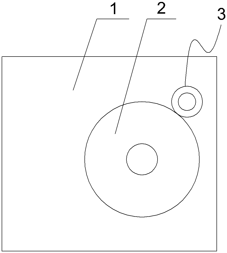
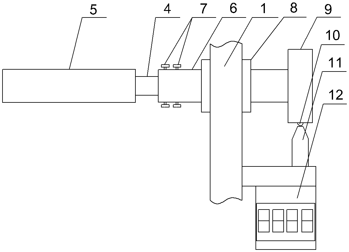
[0009] See figure 1 , figure 2 As shown, an anti-sticking device includes a frame 1, a cutter roller 2 is installed on the frame 1, an oil roller 3 is arranged on the upper side of the cutter roller 2, and the oil roller 3 includes a roller shaft 4 and a sleeve The ring-shaped sponge body 5 on the roller shaft 4, the outer peripheral surface of the sponge body 5 is coated with a silicone oil layer or a release agent layer, the outer peripheral surface of the sponge body 5 is attached to the cutter roller 2, and the end of the roller shaft 3 is embedded in the At one end of the casing 6 , a locking screw 7 for fixing the roller shaft 4 is installed on the casing 6 , and the casing 6 is connected to a bearing 8 installed on the frame 1 . The other end of the bushing 6 runs through the frame 1 and is equipped with a counting disc 9, the outer peripheral surface of the counting disc 9 is equipped with an induction head 10, and a photoelectric sensor 11 corresponding to the induc...


PUM


Abstract

The invention relates to the technical field of product cutting, in particular to an anti-bonding device which can effectively prevent bonding of residual glue on rollers. The anti-bonding device comprises a frame; and a cutter roller is mounted on the frame. The anti-bonding device is characterized in that an oil roller is arranged on one side above the cutter roller; the oil roller comprises a roller shaft, and an annular sponge body sleeving the roller shaft; a silicone oil layer or a mold releasing agent layer are coated on the outer peripheral surface of the sponge body; the outer peripheral surface of the sponge body is bonded with the cutter roller; the end part of the roller shaft is clamped at one end of a sleeve; a locking screw for fixing the roller shaft is mounted on the sleeve; and the sleeve is connected to and mounted on a bearing of the frame.

Description

technical field [0001] The invention relates to the technical field of product cutting, in particular to an anti-sticking device. Background technique [0002] Shaft-knife die-cutting machine is a kind of rapid mass production equipment with high speed and high production speed. It is more suitable for cutting adhesive-backed products. There is a layer of glue on the back of adhesive-backed products. When using shaft-knife die-cutting machine When it is cut, the residual glue on the cut off waste material will adhere to the roller, thereby affecting the subsequent cutting effect. Contents of the invention [0003] In order to solve the problem of sticking glue on the roller, the present invention provides an anti-adhesive device, which can effectively prevent the sticking of residual glue on the roller. [0004] Its technical scheme is as follows: an anti-sticking device, which includes a frame, and a cutter roller is installed on the frame, and it is characterized in tha...

Claims


Application Information

Patent Timeline
IPC IPC(8): B26F1/44
CPCB26F1/44
Inventor 程张宽
Owner 无锡积捷光电材料有限公司
Why Eureka
Try Eureka