Sponge urban facility monitoring and time-lapse photography camera stabilizing device and application method

A sponge city and time-lapse photography technology, which is applied in the direction of supporting machines, mechanical equipment, machines/stands, etc., can solve problems such as time-consuming and laborious adjustment, difficulty in re-erecting, and photo errors

Inactive Publication Date: 2018-11-20
CHINA FIRST METALLURGICAL GROUP
View PDF7 Cites 1 Cited by
  • Summary
  • Abstract
  • Description
  • Claims
  • Application Information

AI Technical Summary

Problems solved by technology

[0006] 1. If the venue is limited, there is no space for the tripod to be erected, and the tripod cannot be moved after the erection is completed, and the disturbance is unstable due to environmental factors.
[0007] 2. Targets that need to be recorded for a long time are restricted by various factors and cannot be shot with a tripod
[0008] 3. Manual recording of tripod erection height, rotation angle and other data has low accuracy, and it is difficult to re-erect according to the recorded height, angle and other data in the next shooting
[0009] 4. When the height and angle change slightly, the recorded photos will have errors, causing the key points to be out of focus, and the later adjustment is time-consuming and laborious

Method used


Image

  • Sponge urban facility monitoring and time-lapse photography camera stabilizing device and application method
  • Sponge urban facility monitoring and time-lapse photography camera stabilizing device and application method

Examples


Embodiment Construction

[0031] In order to make the object, technical solution and advantages of the present invention clearer, the present invention will be further described in detail below in conjunction with the accompanying drawings and embodiments.

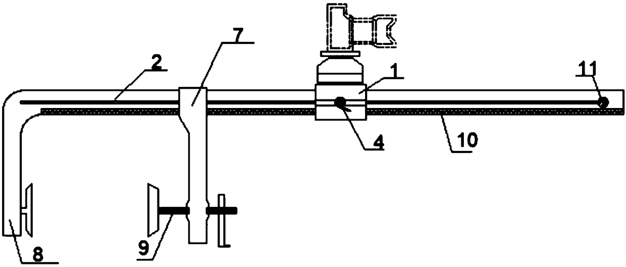
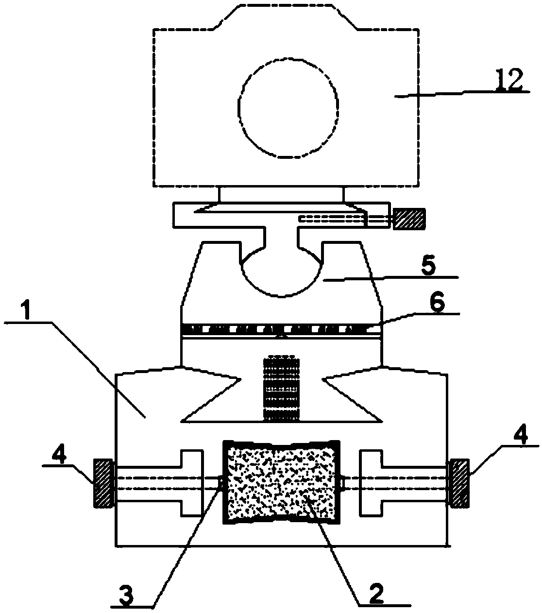
[0032] Such as figure 1 As shown, the present invention provides a camera stabilization device for sponge city facilities monitoring and time-lapse photography, which includes a crossbar 2 , and a crossbar scale 10 is provided at the bottom end of the crossbar 2 . One side of the cross bar 2 is a fixed rod 8, the other side of the cross bar 2 is provided with a limit nail 11, the cross bar 2 is also provided with a locking rod 7, and the bottom end of the locking rod 7 is provided with a locking screw 9, and the cross bar 2, the fixed rod 8. The shape enclosed by the locking rod 7 is a U-shaped groove. The cross bar 2 is equipped with a sliding stabilizing block 1 at a position away from the U-shaped groove, such as figure 2 As shown, the slidin...


PUM


Abstract

The invention discloses a sponge urban facility monitoring and time-lapse photography camera stabilizing device and an application method. The sponge urban facility monitoring and time-lapse photography camera stabilizing device comprises a transverse rod. A transverse rod ruler is arranged at the bottom end of the transverse rod. One side of the transverse rod is provided with a fixing rod, the transverse rod is further provided with a locking rod, and the shape defined by the transverse rod, the fixing rod and the locking rod is a U-shaped groove. The position, away from the U-shaped groove,of the transverse rod is provided with a sliding stabilization block, the sliding stabilization block is internally provided with a gap locking groove containing the transverse rod, and gap adjustingnuts are arranged on the two side walls of the sliding stabilization block and matched with a screw to fix the sliding stabilization block to the transverse rod. A rotary holder is arranged at the top end of the sliding stabilization block, and an angle ruler is arranged below the holder. According to the sponge urban facility monitoring and time-lapse photography camera stabilizing device and the application method, the position is accurately adjusted and recorded according to the ruler on the transverse rod and the angle ruler on the holder on the sliding stabilization block, and when a camera is erected again, original recorded data are utilized for conducting rapid adjustment to the shooting distance, the pitch angle and the horizontal rotation angle.

Description

technical field [0001] The invention relates to the field of photography aids, more specifically, to a camera stabilization device for monitoring and time-lapse photography of sponge city facilities and a method for using the same. Background technique [0002] Time-lapse photography is also called time-lapse photography (English: Time-lapse photography), also known as time-lapse video. It is a time-compressed shooting technology, and it is also called time-lapse video at present. What it takes is a group of photos or videos. Later, through photo concatenation or video frame extraction, the process of minutes, hours, or even days and years is compressed into a short period of time and played as a video. In a time-lapse photography video, the slow changing process of an object or scene is compressed into a short period of time, presenting a strange and wonderful scene that cannot be detected by the naked eye. Time-lapse photography can be considered as a process opposite to...

Claims


Application Information

Patent Timeline
IPC IPC(8): F16M13/02F16M11/04F16M11/12
CPCF16M11/04F16M11/121F16M13/022
Inventor 陈晓伟栗玉鸿吴金平周吉鲁毅
Owner CHINA FIRST METALLURGICAL GROUP
Why Eureka
Try Eureka