
Electronic apparatus unit

a technology of electronic equipment and waterproof housing, which is applied in the direction of electrical equipment casings/cabinets/drawers, coupling device connections, casings/cabinets/drawers, etc., can solve the problems of general purpose connectors that cannot be used, use mold filings, and prior ar

Active Publication Date: 2018-07-26
MITSUBISHI ELECTRIC CORP
View PDF0 Cites 4 Cited by
  • Summary
  • Abstract
  • Description
  • Claims
  • Application Information

AI Technical Summary

Benefits of technology

The invention aims to provide an electronic apparatus unit that has a decreased weight, improved assembly, and a stable waterproof seal gap. The electronic apparatus unit includes a base and a cover, which are fastened together using fastening screws. The fastening surfaces on the base and cover have a seal gap between them that prevents water from entering. The design of the fastening surfaces allows for precise control of the seal gap and ensures an optimal seal. Additionally, the design prevents abnormal deformation of the outer surfaces of the base and cover, while also reducing the width of the electronic apparatus unit. Overall, the invention provides a thinner, lighter, and more robust electronic apparatus unit.

Problems solved by technology

(1) Problems of prior art
Therefore, an outsert-molding machine, to mold the resin, is required in the assembly step, and use of mold filing is inappropriate for such an environment as an engine compartment of an automobile, where such problems as solder peeling off electronic components due to heat and vibration, or separation and falling off of the base and cover are possible.
Further, in this electronic circuit unit, the cover and the connector are integrally molded, hence when the circuit board size is changed, the die of the connector portion must be recreated, so here a general purpose connector cannot be used.

Method used


Image

  • Electronic apparatus unit
  • Electronic apparatus unit
  • Electronic apparatus unit

Examples


embodiment 1

[0026](1) Detailed description of the configuration

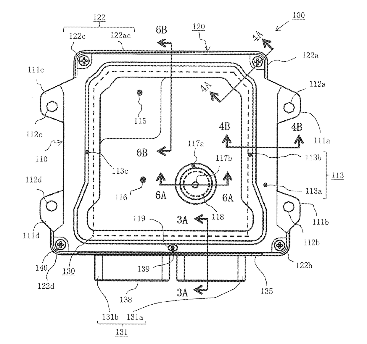
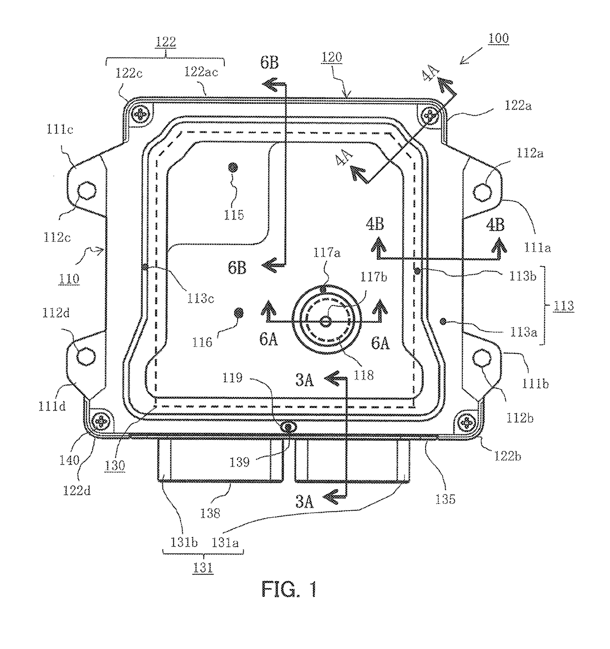
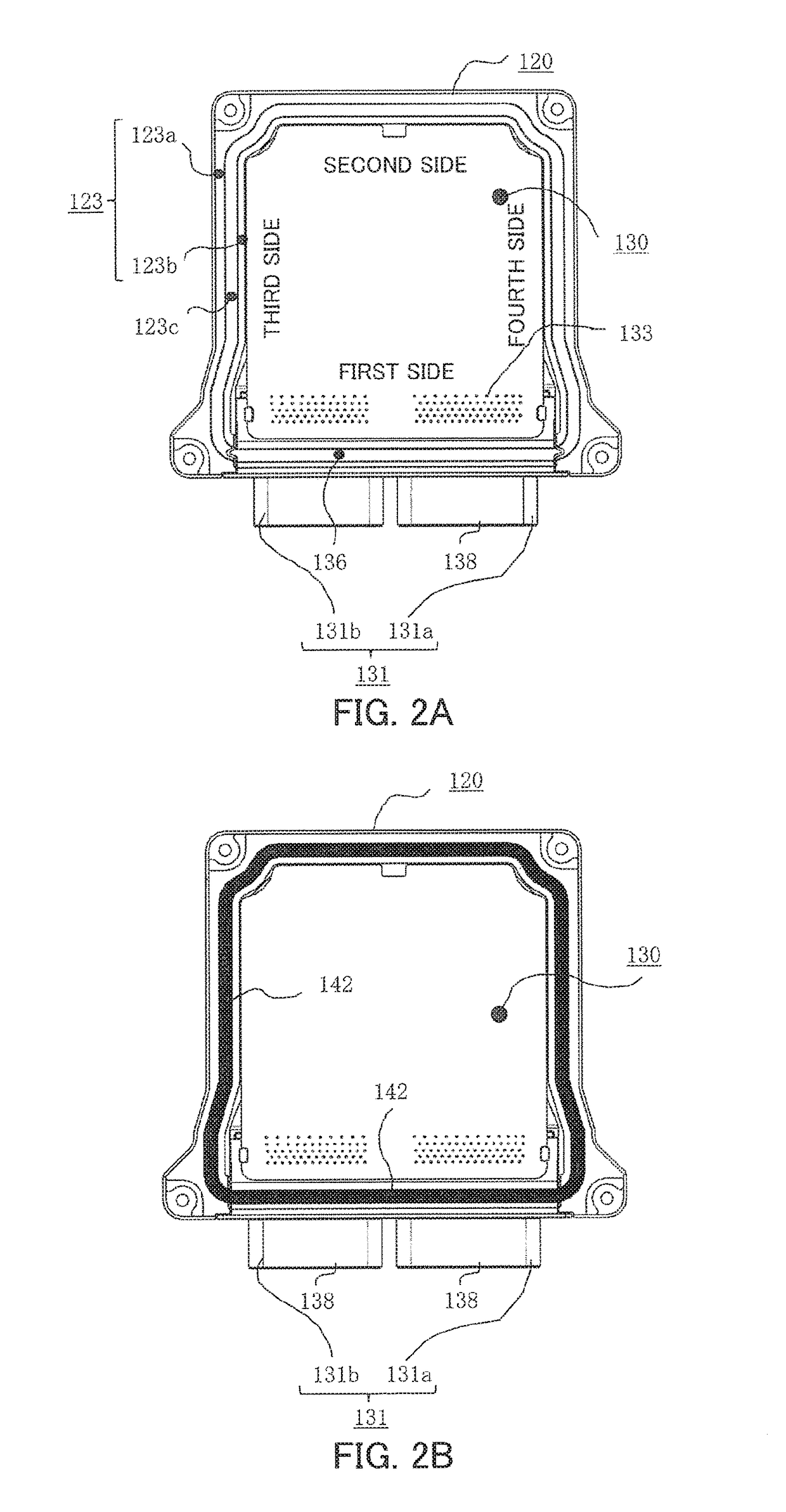
[0027]The configuration of an electronic apparatus unit according to one embodiment of this invention will be described in sequence with reference to: FIG. 1 which is an external view of the rear surface of the electronic apparatus unit, FIG. 2A which is inside plan view of FIG. 1 before applying a second seal material, FIG. 2B which is an inside plan view of FIG. 1 after applying the second seal material, FIG. 3A which is a partial cross-sectional view sectioned at the 3A-3A line indicated by the arrow marks in FIG. 1, and FIG. 3B which is an end view of a connector housing indicated by the arrow mark 3B in FIG. 3A. As depicted in FIG. 1, the electronic apparatus unit 100 is constituted by: a sealed case body in which the base 110 (made of sheet metal) having mounting legs 111a and 111b and mounting legs 111c and 111d on two sides in a second direction, which intersects orthogonally to a first direction that is an insertion / extract...


PUM


Abstract

A second seal material is coated on an annular seal surface constituted by a partition wall of a connector housing and a three-sided outer peripheral surface of a cover, and is joined with an annular base outer peripheral surface on the base, and the cover and the base are integrated with fastening screws at the four corners, and hold the three sides of a circuit board therebetween. Fastening surfaces of the base are embossed with a first depth so that bending strength is reinforced whereby a stable seal gap is generated, and corner outer walls and a connection outer wall are disposed at four corners and one side of the cover, so as to generate a retention gap to prevent outflow of the second seal material.

Description

BACKGROUND OF THE INVENTION1. Field of the Invention[0001]The present invention relates to an improvement of a waterproof type electronic apparatus unit which is suitable for an on-vehicle electronic control apparatus installed in an engine compartment, for example.2. Description of the Related Art[0002]There is a waterproof type electronic apparatus unit configured to house a circuit board, on which a plurality of circuit components and a connector housing (tall component) are mounted, in a sealed case body, allowing a part of the connector housing to be exposed from the case body so as to connect with a mating connector. The case body that houses this electronic apparatus unit is constituted by a case having a space to house the circuit board and a flat cover which covers the case, where the case and the flat cover are secured by screws, or is constituted by a flat base, on which the circuit board is mounted, and a deep cover which covers the base. Mounting legs are installed on e...

Claims


Application Information

Patent Timeline
Patent Type & Authority Applications(United States)
IPC IPC(8): H05K5/00H01R13/52H01R13/516H05K5/03H05K7/20H05K5/02
CPCH05K5/0052H05K5/0056H05K5/006H01R13/5202H01R13/516H05K5/03H05K5/0008H05K7/20445H05K5/0213H01R12/724H01R12/7064H01R12/727H05K5/0069H05K1/0203
Inventor NURIYA, NOBUAKI
Owner MITSUBISHI ELECTRIC CORP
Learn More