Cooking utensil

A technology of cooking utensils and stirring paddles, which is applied in the field of cooking utensils, can solve the problems that upper and lower ingredients cannot be mixed evenly, taste is affected, and seasonings cannot be mixed evenly.

Inactive Publication Date: 2019-04-19
JOYOUNG CO LTD
View PDF11 Cites 4 Cited by
  • Summary
  • Abstract
  • Description
  • Claims
  • Application Information

AI Technical Summary

Problems solved by technology

[0003] However, because the stirring method is rotating and stirring, the ingredients in the pot often have the problem of turning circles. The upper layer of ingredients is always on the upper layer, and the lower layer of ingredients is alw

Method used


Image

  • Cooking utensil
  • Cooking utensil
  • Cooking utensil

Examples


Embodiment approach 1

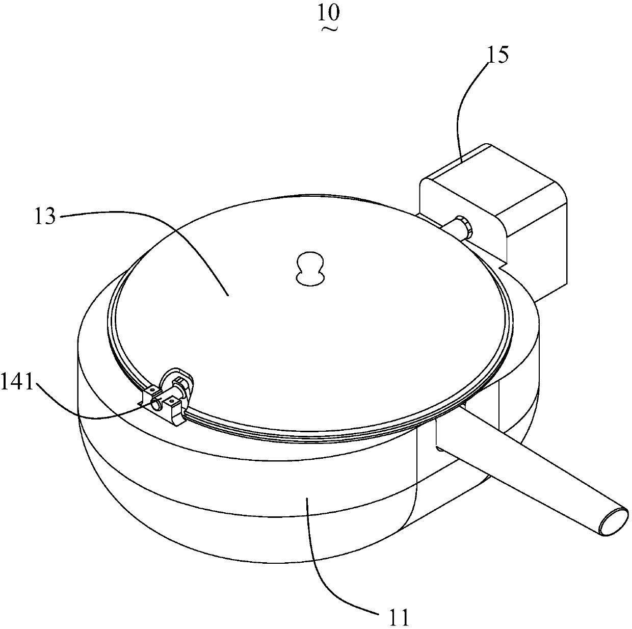
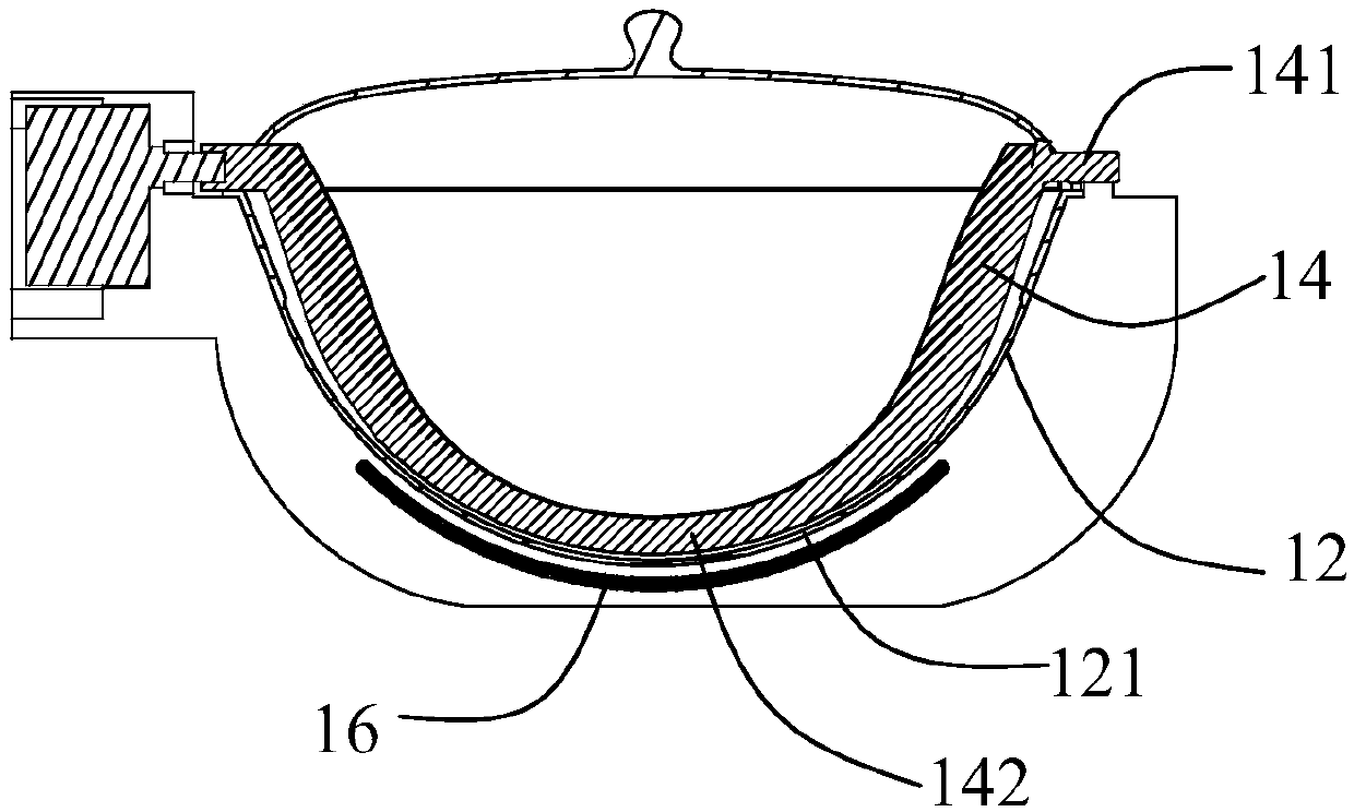
[0042] see figure 1 and figure 2 The schematic diagram of the first preferred embodiment of the cooking utensil, the cooking utensil 10 includes a base shell 11, a pot body 12, a pot cover 13, a stirring paddle 14, and a driving mechanism 15 for driving the stirring paddle 14 to move, the pot body 12 is embedded in the base shell 11, the pot cover 13 is fastened on the pot body 12, the stirring paddle 14 is arranged in the pot body 12 in a laterally swingable manner, and the driving mechanism 15 is installed on the base shell 11. In this embodiment, the cooking utensil 10 also includes a heating device 16, which heats the cup body. The heating device 16 can be electromagnetic heating or electric heating tube heating. adapt.

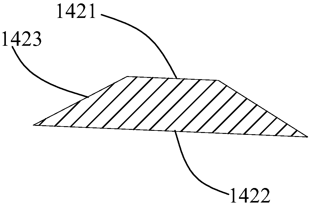
[0043]In this embodiment, both ends of the stirring paddle 14 are provided with rotating shafts 141 , and the rotating shafts 141 are installed on the machine base shell 11 , and the driving mechanism 15 drives one of the rotating shafts 141 to drive t...

Embodiment approach 2

[0063] see Figure 10 The schematic diagram of the second preferred embodiment of the cooking utensil. The difference between the cooking utensil 20 and the cooking utensil 10 is that only one end of the stirring paddle 21 is provided with a rotating shaft 211, and the driving mechanism 15 drives the rotating shaft to drive the stirring paddle 21 Swinging back and forth, the other end of the stirring paddle 21 extends to a region higher than the pot body 12 covered by the heating device 16 .

[0064] The stirring paddles 21 may be various types of paddle structures in Embodiment 1.

[0065] The stirring paddle 21 is fixedly installed at one end, so that the installation structure is simple and easy to install, and it is convenient for users to disassemble and assemble; in addition, since the area covered by the heating device 16 is the area with the highest temperature, the other end of the stirring paddle 21 extends higher than the pot covered by the heating device. The area...


PUM

PropertyMeasurementUnit
Widthaaaaaaaaaa

Abstract

The invention relates to a cooking utensil which comprises a pot, a pot lid, a stirring paddle and a driving mechanism. The stirring paddle can be driven by the driving mechanism to move, and is arranged in the pot in such a manner that the stirring paddle can transversely swing; the stirring paddle at least comprises a cambered section in the length direction, the inner wall of the pot comprisesa cambered surface, the cambered surface adapts to the shape of the cambered section when the cambered section swings, the cambered section comprises a top surface, a bottom surface and side surfaces,the side surfaces are connected with the top surface and the bottom surface, and included angles ranging from 0 degrees to 70 degrees are formed by the bottom surface and the side surfaces. Comparedwith the prior art, the cooking utensil has the advantages that upper and lower layers of food materials can be continuously repositioned to be repeatedly stir-fried, accordingly, the food materials,spices and the like can be uniformly mixed with one another, the cooking degree can be greatly upgraded, and mouth feel can be greatly enhanced.

Description

technical field [0001] The present invention relates to a cooking appliance. Background technique [0002] Existing cooking machines usually have functions such as automatic heating of oil, automatic stir-frying, and automatic temperature control, and usually include a machine base, a pot body, a stirring paddle, and a pot cover. The stirring paddle rotates to drive the ingredients in the pot to stir fry. [0003] However, because the stirring method is rotating and stirring, the ingredients in the pot often have the problem of turning circles. The upper layer of ingredients is always on the upper layer, and the lower layer of ingredients is always on the lower layer. On the one hand, it is easy to cause the problem of sticking to the pan, on the other hand, the ingredients cannot be mixed evenly, which affects the taste, and the seasoning cannot be mixed evenly with the ingredients. Contents of the invention [0004] In view of this, it is necessary to provide a cooking...

Claims


Application Information

Patent Timeline
IPC IPC(8): A47J27/00A47J36/00
CPCA47J27/002A47J36/00
Inventor 王旭宁刘孝碧
Owner JOYOUNG CO LTD
Why Eureka
Try Eureka