Light source module and lamp

A light source module and lamp technology, applied in the field of lighting, can solve the problem of high cost, achieve the effects of reducing heat dissipation requirements, saving raw materials, and reducing product costs

Pending Publication Date: 2018-11-20
SUZHOU OPPLE LIGHTING +1
View PDF9 Cites 1 Cited by
  • Summary
  • Abstract
  • Description
  • Claims
  • Application Information

AI Technical Summary

Problems solved by technology

[0005] Therefore, the cost of this heat dissipation structure in the related art is relatively high

Method used


Image

  • Light source module and lamp
  • Light source module and lamp
  • Light source module and lamp

Examples


Embodiment Construction

[0044] In order to make the purpose, technical solution and advantages of the present application clearer, the technical solution of the present application will be clearly and completely described below in conjunction with specific embodiments of the present application and corresponding drawings. Apparently, the described embodiments are only some of the embodiments of the present application, rather than all the embodiments. Based on the embodiments in this application, all other embodiments obtained by persons of ordinary skill in the art without making creative efforts belong to the scope of protection of this application.

[0045] The technical solutions provided by various embodiments of the present application will be described in detail below in conjunction with the accompanying drawings.

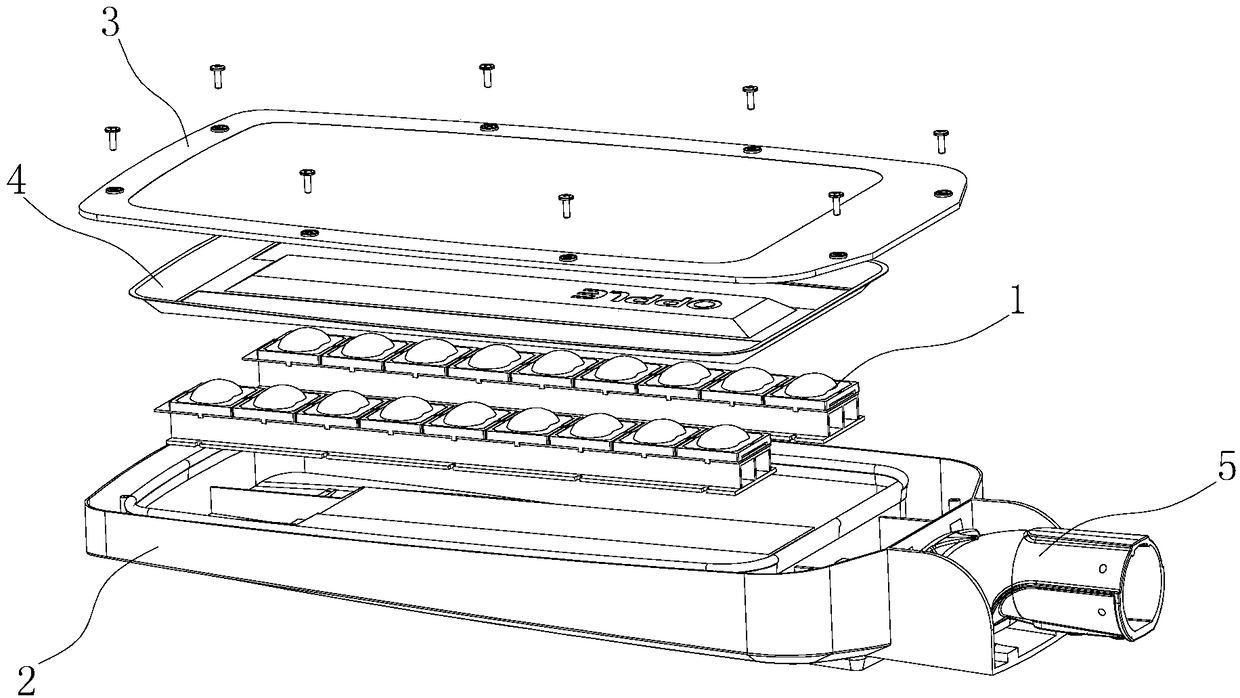
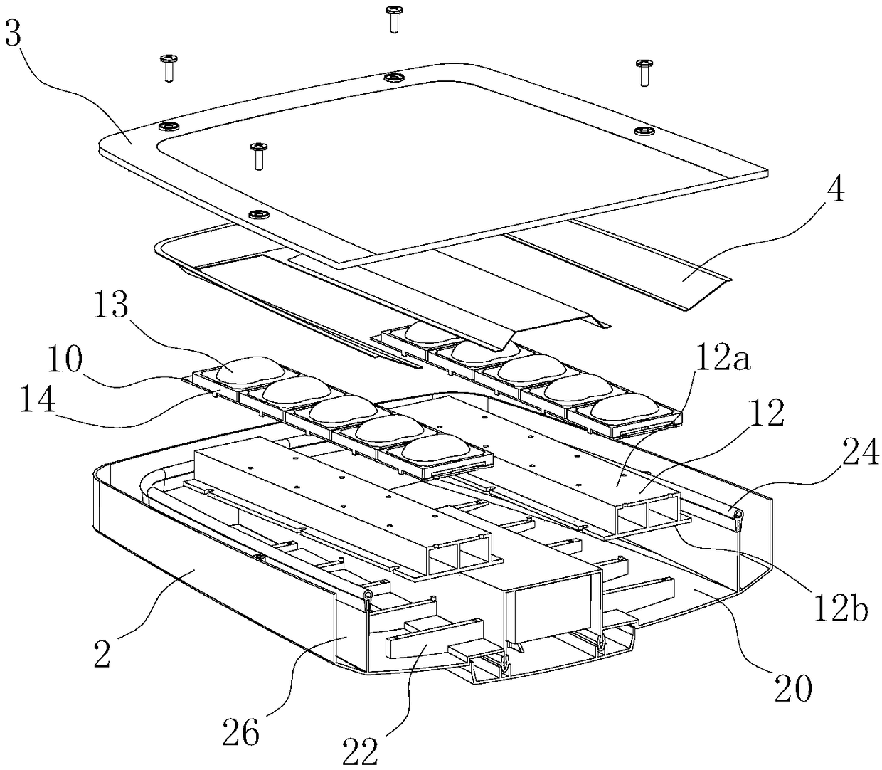
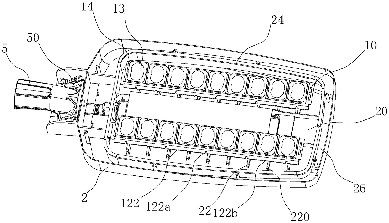
[0046] The embodiment of the present application discloses a lamp, such as Figure 1 to Figure 6 As shown, it includes a light source module 1 and a housing 2 . The light source ...


PUM


Abstract

The invention discloses a light source module and a lamp. The light source module comprises a light source panel, a light-emitting unit and a heat conducting part. The light source panel is provided with a first surface and a second surface which are separated from each other. The light-emitting unit is arranged on the first surface, the heat conducting part is provided with a first heat conducting face and a second heat conducting face which are separated, and the first heat conducting face is attached to the second surface. The lamp comprises a shell and the light source module. The shell isprovided with an assembly cavity, and a plurality of inner cooling fins are arranged in the assembly cavity. The light source module is arranged in the assembly cavity, and the second heat conductingface is attached to the inner cooling fins. According to the light source module and the lamp, the product cost can be comprehensively reduced.

Description

technical field [0001] The present application relates to the technical field of lighting, in particular to a light source module and a lamp. Background technique [0002] In the field of lighting, the heat dissipation methods of lamps and lanterns mainly include external heat dissipation fin type and internal heat dissipation fin type. The external heat dissipation fin type heat dissipation structure is provided with heat dissipation fins on the outside of the housing. This heat dissipation structure has a good heat dissipation effect, but it is not conducive to industrial design and shape, and its self-cleaning ability is poor. The internal heat dissipation fin type heat dissipation structure is to install heat dissipation fins on the inner side of the shell. This heat dissipation structure hides the heat dissipation fins inside the shell, which is not only conducive to industrial design, but also has excellent self-cleaning ability. Therefore, it is used more extensive. ...

Claims


Application Information

Patent Timeline
Patent Type & Authority Applications(China)
IPC IPC(8): F21K9/20F21V5/04F21V17/16F21V19/00F21V29/503F21V29/74F21V29/89F21Y115/10
CPCF21K9/20F21V5/04F21V17/164F21V19/001F21V29/503F21V29/74F21V29/89F21Y2115/10
Inventor 朱增龙卫庆军刘动王洪波
Owner SUZHOU OPPLE LIGHTING
Why Eureka
Try Eureka