Intercooling pipeline, cooling system, automobile and cooling method of intercooling pipeline

A heat dissipation system and cold pipe technology, which is applied in the fields of intercooler pipelines, heat dissipation systems, automobiles and intercooler pipelines. The effect of multiple constraints

Pending Publication Date: 2018-11-23
北京长城华冠汽车技术开发有限公司
View PDF0 Cites 1 Cited by
  • Summary
  • Abstract
  • Description
  • Claims
  • Application Information

AI Technical Summary

Problems solved by technology

[0009] The purpose of the present invention is to provide an intercooler pipeline, heat dissipation system, automobile and intercooler pipeline heat dissipation method, so as to alleviate the problem of excessive dependence on intercoolers in existing vehicles

Method used


Image

  • Intercooling pipeline, cooling system, automobile and cooling method of intercooling pipeline
  • Intercooling pipeline, cooling system, automobile and cooling method of intercooling pipeline
  • Intercooling pipeline, cooling system, automobile and cooling method of intercooling pipeline

Examples


Embodiment 1

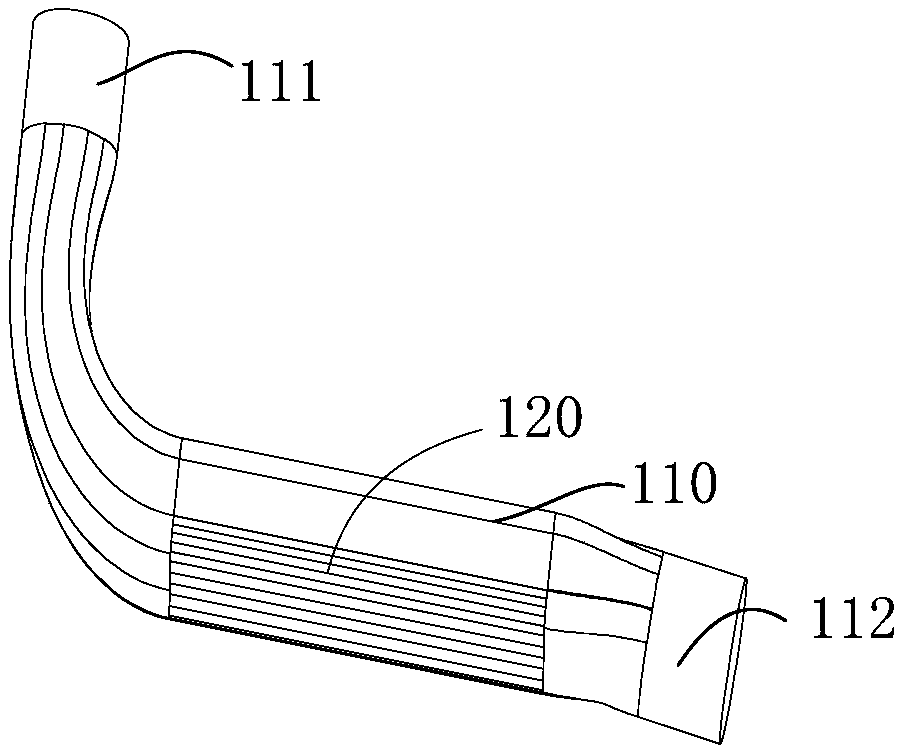
[0047] This example provides an intercooler pipeline, please refer to figure 1 , figure 1 The isometric view of the intercooling pipeline provided by the embodiment of the present invention. It includes a pipeline main body 110 and a heat dissipation structure 120 arranged on the pipeline main body 110,

[0048] The pipeline body 110 includes an inlet port 111 and an outlet port 112 , the inlet port 111 communicates with the air outlet of the turbocharger 630 , and the outlet port 112 communicates with the air inlet of the intercooler 200 .

[0049]The high-temperature gas output by the turbocharger 630 flows to the intercooling pipeline 100, and the external air directly acts on the intercooling pipeline 100. The heat dissipation structure 120 exchanges heat between the high-temperature gas and the external air, and passes through the intercooling pipeline 100 to dissipate heat in the first stage. Afterwards, it flows to the intercooler 200 , and then flows to the air intak...

Embodiment 2

[0061] This embodiment is another preferred solution paralleled with Embodiment 1. The technical solution disclosed in Embodiment 1 outside the distinguishing technical features belongs to the scope disclosed in this embodiment. Embodiment 1 outside the distinguishing technical features The disclosed technical solutions will not be described repeatedly.

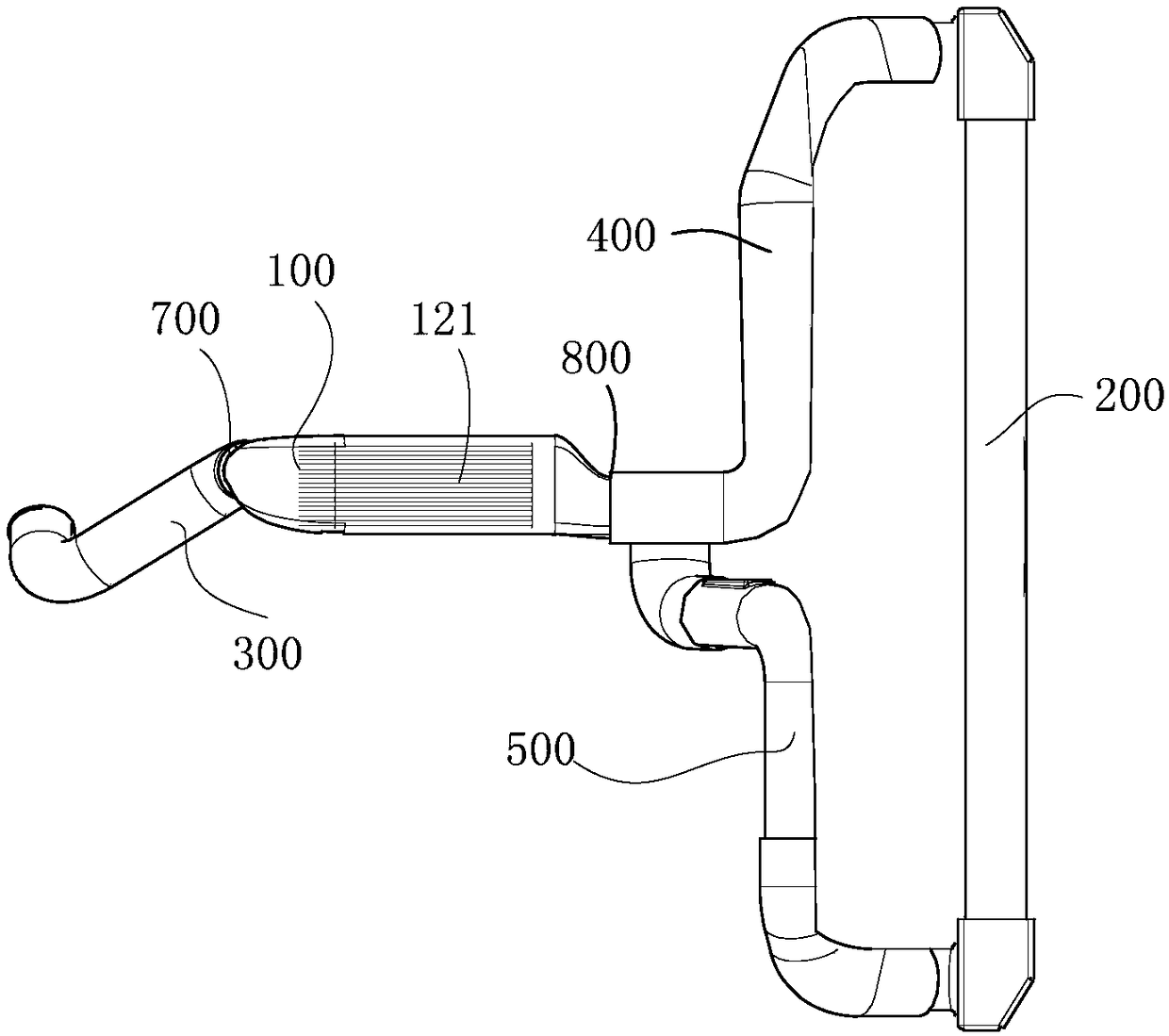
[0062] This embodiment provides a cooling system, please refer to Figure 1 to Figure 2 , figure 1 An axonometric view of the intercooling pipeline provided for the embodiment of the present invention; figure 2 The bottom view of the heat dissipation system provided by the embodiment of the present invention includes an intercooler pipeline 100 .

[0063] The high-temperature gas output by the turbocharger 630 flows to the intercooler pipeline 100, the outside air directly acts on the intercooler pipeline 100, passes through the intercooler pipeline 100 to dissipate heat, and then flows to the intercooler 200, and then pas...

Embodiment 3

[0071] This embodiment is another preferred solution juxtaposed with Embodiment 1 to Embodiment 2. The technical solutions disclosed in Embodiment 1 to Embodiment 2 other than distinguishing technical features belong to the scope disclosed in this embodiment. The technical solutions disclosed in Embodiment 1 to Embodiment 2 other than the technical features will not be described again.

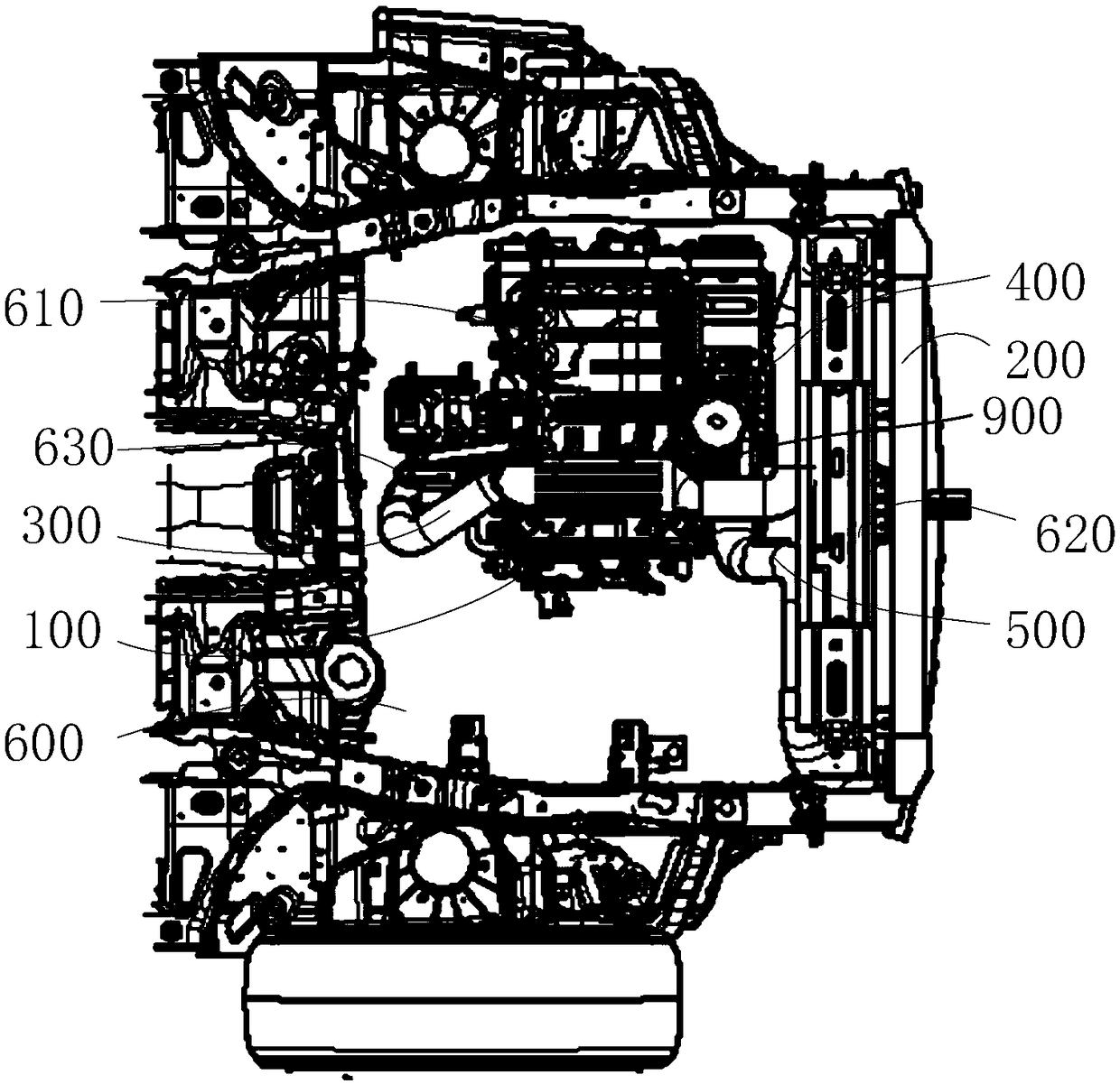
[0072] This embodiment provides a car, please refer to Figure 1 to Figure 3 , figure 1 An axonometric view of the intercooling pipeline provided for the embodiment of the present invention; figure 2 The bottom view of the cooling system provided for the embodiment of the present invention; image 3 The bottom view of the engine compartment in the car provided by the embodiment of the present invention. Including cooling system and engine compartment 600.

[0073] An engine 610, a bumper 620 and a turbocharger 630 are arranged in the engine compartment 600; the intercooler pipeline 100 is...


PUM


Abstract

The invention relates to the field of automobiles, in particular to an intercooling pipeline, a cooling system, an automobile and a cooling method of the intercooling pipeline. The intercooling pipeline, the cooling system, the automobile and the cooling method are used for solving the problem of excessive dependence on intercoolers of existing automobiles. The intercooling pipeline comprises a main pipeline body and a cooling structure arranged on the main pipeline body. The main pipeline body comprises an inlet end and an outlet end, the inlet end is communicated with a turbocharging gas outlet, and the outlet end is communicated with a gas inlet of the intercooler. High-temperature gas output by a turbocharger flows to the intercooling pipeline, external air directly acts on the intercooling pipeline, and the gas flows to an intercooler after primary cooling of the intercooling pipeline, and then flows to an engine after secondary cooling of the intercooler. According to the intercooling pipeline, the cooling system, the automobile and the cooling method, the high-temperature gas is cooled before entering the intercooler, excessive dependence of the high-temperature gas on the intercooler is lowered, the requirement of the whole automobile for the cooling capability of the intercooler is lowered, and then the aim of lowering excessive constraints of the intercooler on arrangement space and the shape of the front end of a vehicle is achieved.

Description

technical field [0001] The invention relates to the field of automobiles, in particular to an intercooler pipeline, a heat dissipation system, an automobile and a heat dissipation method for the intercooler pipeline. Background technique [0002] With the improvement of consumers' living standards, consumers have put forward more and more strict requirements on the performance and appearance of automobiles. As the main structure of a car, the engine affects many performance indicators of the car. [0003] The turbocharged engine has been widely used in many models, and it can deliver more air to the engine at the same time, and form a mixed gas with fuel for combustion. However, after the turbocharger compresses the air, the temperature of the air rises significantly. Therefore, in order to improve the combustion efficiency, the heated air needs to undergo a cooling process before it can be transported into the engine for combustion. Currently, on models with turbocharged ...

Claims


Application Information

Patent Timeline
Patent Type & Authority Applications(China)
IPC IPC(8): F02M35/10F02B29/04B60K13/02B60K11/06
CPCB60K11/06B60K13/02F02B29/0412F02B29/0456F02M35/10091F02M35/10268Y02T10/12
Inventor 那明赫牛艳兵牛新杰代宏伟潘菲
Owner 北京长城华冠汽车技术开发有限公司
Why Eureka
Try Eureka