Novel high-frequency high-performance power supply

A high-efficiency, power supply technology, applied in the direction of electrical components, power supply technology, electrostatic separation, etc., can solve the problems of large energy consumption loss, high heat of components, etc., and achieve the effect of improving energy efficiency ratio, reducing heat dissipation, and reducing energy consumption

Inactive Publication Date: 2016-08-10
浙江连成环保科技有限公司
View PDF0 Cites 0 Cited by
  • Summary
  • Abstract
  • Description
  • Claims
  • Application Information

AI Technical Summary

Problems solved by technology

[0004] Conventional inverters use electronic components such as MOS field effect transistors or IGBT insulated gate bipolar transistors to realize current commutation. Loss loss, and it will cause excessive heat of components, so a lot of auxiliary heat dissipation equipment is needed

Method used


Image

  • Novel high-frequency high-performance power supply
  • Novel high-frequency high-performance power supply
  • Novel high-frequency high-performance power supply

Examples


Embodiment Construction

[0016] The present invention will be described in further detail below in combination with specific embodiments and accompanying drawings.

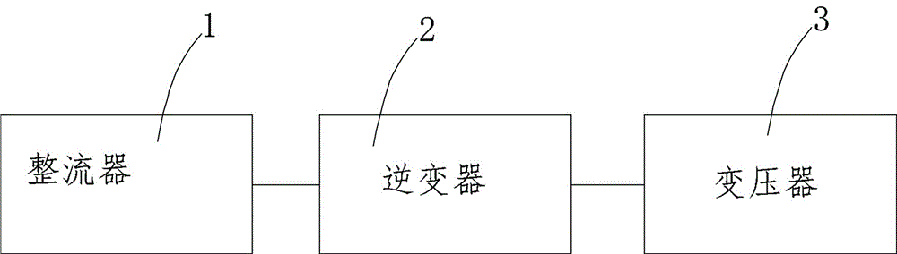
[0017] see figure 1 , a new high-frequency high-efficiency power supply, including a rectifier 1, an inverter 2 and a transformer 3.

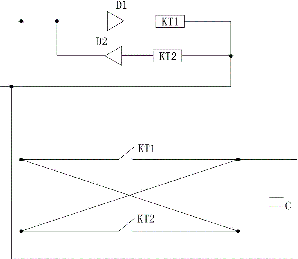
[0018] see figure 2 , the rectifier 1 includes a first diode D1, a second diode D2, a first relay KT1, a second relay KT2 and a capacitor C. The coil of one relay KT1 is connected and then connected to the neutral line, and the other circuit is connected to the coil of the second diode D2 and the second relay KT2 in turn and then connected to the neutral line. The first diode D1 and the second two The pole tube D2 is set in reverse, the live wire of the external power supply is connected to one end of the switch of the first relay KT1, the other end of the switch of the first relay KT1 is connected to the inverter 2, the two ends of the switch of the second relay KT2 are connected to the two ends of the...


PUM


Abstract

A new type of high-frequency high-efficiency power supply, including a rectifier, an inverter and a transformer. The inverter includes two input brushes and two output brushes of the motor, and a commutator and two output electrodes are arranged on the shaft of the motor. , the commutator is a collar fixed on the rotating shaft and rotates together with the rotating shaft, the commutator is provided with a pair of conductive blocks at 180 degrees to each other, and the two input brushes are connected to the commutating The two input brushes are in contact with each other, the two conductive blocks are respectively connected to the two output electrodes, and the two output brushes are respectively connected to the two output electrodes. In this way, no electronic components are used in this circuit, and there is no other loss except the energy consumed by the motor and line loss. Therefore, when it is suitable for high-power applications, the efficiency is much higher than that of ordinary inverters. Due to the improved energy efficiency ratio, the heat dissipation is also reduced, and the requirements of the power supply for heat dissipation are also greatly reduced.

Description

technical field [0001] The invention relates to the technical field of electrostatic dust removal, in particular to a power supply for electrostatic dust removal. Background technique [0002] The working principle of the electrostatic precipitator is to use the high-voltage DC uneven electric field to ionize the gas molecules in the flue gas, generate a large number of electrons and ions, move to the poles under the action of the electric field force, and encounter the dust particles in the air flow during the movement. It is charged, and the charged dust is separated from the airflow under the action of the electric field force and moves to the polar plate or polar line with the opposite polarity. When the charged dust reaches the polar plate or polar line, it is adsorbed on the polar plate or polar line by electrostatic force, and passes through The rapping device makes the dust fall into the ash hopper to purify the flue gas. [0003] A general electrostatic precipitato...

Claims


Application Information

Patent Timeline
Patent Type & Authority Applications(China)
IPC IPC(8): H02M7/00B03C3/66
CPCH02M7/00B03C3/66
Inventor 陈文臣李呈森
Owner 浙江连成环保科技有限公司
Why Eureka
Try Eureka