Pulling force test method for ship lashing eye plate

A tensile test and cable eye plate technology, applied in the field of shipbuilding, can solve the problems of reduced test efficiency, poor test result accuracy, large error, etc., to achieve accurate test data, improve test speed and quality, and save sampling and multiple times. The effect of the test procedure

Active Publication Date: 2018-11-20
GUANGZHOU SHIPYARD INTERNATIONAL LTD
View PDF15 Cites 0 Cited by
  • Summary
  • Abstract
  • Description
  • Claims
  • Application Information

AI Technical Summary

Problems solved by technology

This tensile test has the following defects: 1. The sampling method is used for the tensile test, and the error is large, and the accuracy of the test results is poor; 2. The more tests prolong the test time and reduce the efficiency of the test; 3. The poor accuracy of the test results will directly Affects the use of the lanyard eye plate

Method used


Image

  • Pulling force test method for ship lashing eye plate
  • Pulling force test method for ship lashing eye plate
  • Pulling force test method for ship lashing eye plate

Examples


Embodiment Construction

[0024] In order to make the technical problems solved by the present invention, the technical solutions adopted and the technical effects achieved clearer, the technical solutions of the embodiments of the present invention will be further described in detail below in conjunction with the accompanying drawings. Obviously, the described embodiments are only the technical solutions of the present invention. Some, but not all, embodiments. Based on the embodiments of the present invention, all other embodiments obtained by those skilled in the art without creative efforts fall within the protection scope of the present invention.

[0025] In the description of the present invention, unless otherwise clearly specified and limited, the terms "connected", "connected" and "fixed" should be understood in a broad sense, for example, it can be a fixed connection, a detachable connection, or an integrated ; It can be a mechanical connection or an electrical connection; it can be a direct...


PUM


Abstract

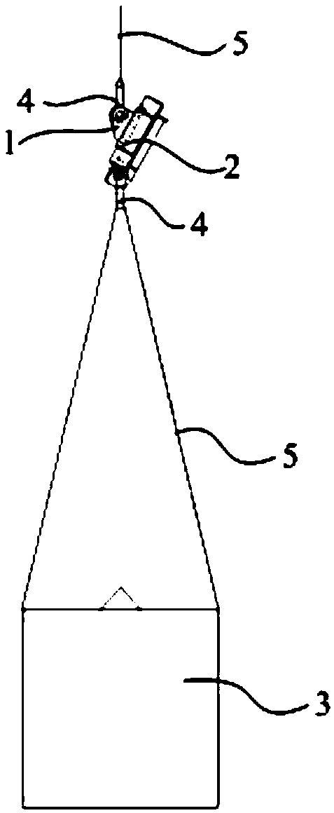
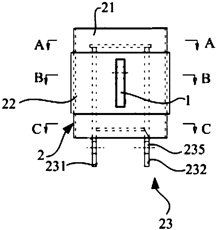
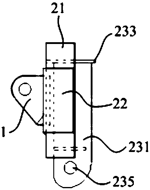
The invention discloses a pulling force test method for a ship lashing eye plate. A test tool which includes an installation surface the same with the surface of a mast to be welded of the lashing eyeplate is provided, a plugging groove is formed in the installation surface, the lashing eye plate is welded into the plugging groove, the lashing eye plate or the test tool is fixed in position, a test pulling force is applied to the test tool or the lashing eye plate, the rated load of the lashing eye plate<= the test pulling force<= the breaking limit load of the lashing eye plate, and after standing time T, the test pulling force is removed, and weld seam detection and surface detection are carried out on the lashing eye plate. The lashing eye plate is welded to the test tool as to the mast, pulling force test can be carried out on the lashing eye plate directly, non-destructive test is realized, more accurate test data can be obtained, sampling or repeated test is omitted, and the test speed and quality are improved; and whether the lashing eye plate satisfies requirements after the pulling force test can be determined via weld seam detection and surface detection.

Description

technical field [0001] The invention relates to the technical field of shipbuilding, in particular to a tensile test method for a ship's mooring eye plate. Background technique [0002] The rated load of the lanyard eye plate of the sailing ship (that is, the maximum working load that the lanyard eye plate can withstand when working) is 9.5T, and the installation node is a method of opening a hole on the mast and inserting welding. The eye plate of the lanyard is a strong stress member. According to the requirements of the classification society, such a strong stress member needs to be subjected to a tensile test before use. The tensile test of the existing lanyard eye plate is to carry out the sample tensile test in the laboratory after sampling. In order to improve the accuracy of the test, more than ten groups of samples are usually prepared for the test, and the tensile test is performed on each group of samples one by one. And form a record, and finally determine wheth...

Claims


Application Information

Patent Timeline
Patent Type & Authority Applications(China)
IPC IPC(8): G01L5/04
CPCG01L5/04
Inventor 彭善胤洪小彬张丽华郭建杰王文
Owner GUANGZHOU SHIPYARD INTERNATIONAL LTD
Why Eureka
Try Eureka