
Woods and wooden composite material shearing modulus non destructive checkers
A composite material and shear modulus technology, applied in the direction of measuring devices, wood testing, material inspection products, etc., can solve the problems of waste, time-consuming, expensive, etc., to ensure product quality, convenient and fast operation, and good detection effect Effect
- Summary
- Abstract
- Description
- Claims
- Application Information
AI Technical Summary
Problems solved by technology
Method used
Image

Examples
Embodiment Construction
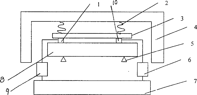
[0009] The best embodiment of the present invention will be described in detail below in conjunction with the accompanying drawings. The non-destructive testing device for shear modulus of wood and wood composite materials includes sensors 1 and 10, signal amplifiers 9 and 6, and a fast Fourier transform (FFT) analyzer 7, and a compression spring 2 is installed on the inner upper wall of the frame 4, and a plastic plate 3 The end face is connected with the lower end face of the compression spring 2, and the plastic plate 3 is installed inside the frame 4; the left sensor 1 and the right sensor 10 are installed on the left and right sides of the lower end face of the plastic plate 3 respectively; the foam support block 5 is equipped with Installed below the left and right side sensors 1 and 10; the wires respectively connect the left side sensor 1, the left side signal amplifier 9, the fast Fourier transform FFT analyzer 7 and the right side sensor 10, the right side signal ampl...
PUM
 Abstract
Description
Claims
Application Information