Hand-pushing smoke treatment device

A kind of processing equipment and hand-push technology, which is applied in the direction of dispersed particle separation, chemical instruments and methods, and the use of liquid separation agents, etc., can solve the problems of fewer procedures, inconvenient operation, and large floor space, so as to improve the working speed, Improve work efficiency and facilitate maintenance

Inactive Publication Date: 2018-11-23
芜湖鑫霖森椽环保科技有限公司
3 Cites 0 Cited by

AI-Extracted Technical Summary

Problems solved by technology

[0002] In modern production and life, the problem of smog is an unavoidable problem that people cannot avoid. Generally, the problems in various workshops cannot be solved well, which seriously affects the production and the health of the staff. Traditional processing equipment can only reduce a certain amount and due to the simple treatment process and few procedures, it is impossible to puri...

Method used

It should be noted that, the present invention is a kind of hand-push smog processing equipment, and in use, the user starts the spray head inside the air pump 8 and the high-efficiency spray box 3 by pressing the start switch 14, Then use the handrail 12 to push the device to the area where the smog is thicker, and carry out smog treatment. In the process of handling the smog, you can also understand the working status of the equipment through the work reminder light 15, and you can add water or change the inside of the water storage tank 1 through the water filling port 2. Water is u...

Abstract

The invention discloses a hand-pushing smoke treatment device, comprising a water storage tank, wherein a water adding hole is fixedly arranged on the outer surface of the upper end of the water storage tank, a high-efficiency spray box is arranged on the rear end, close to the water adding hole of the outer surface of the upper end of the water storage tank, the outer surface of the upper end ofthe high-efficiency spray box is provided with an air inlet, a lead-in air pipe is arranged on the one side, close to the high-efficiency spray box of the outer surface of the upper end of the water storage tank, an activated carbon adsorption tank is arranged on the one side, close to the lead-in air pipe of the outer surface of the upper end of the water storage tank, and the outer surface of the upper end of the activated carbon adsorption tank is provided with an air outlet. The hand-pushing smoke treatment device, provided with the high-efficiency spray box, the activated carbon adsorption box, rolling shafts and balls, can efficiently deposit smoke into water and then filter the smoke through the activated carbon adsorption tank to remove harmful impurities, so as to better purify the air; the device can be easily moved by the rolling shafts and the balls, to adapt to different working environments, thereby having better application prospects.

Application Domain

Using liquid separation agent

Technology Topic

Activated carbonWater storage tank +5

Image

  • Hand-pushing smoke treatment device
  • Hand-pushing smoke treatment device
  • Hand-pushing smoke treatment device

Examples

  • Experimental program(1)

Example Embodiment

[0017] In order to make the technical means, creative features, objectives and effects achieved by the present invention easy to understand, the present invention will be further explained below in conjunction with specific embodiments.
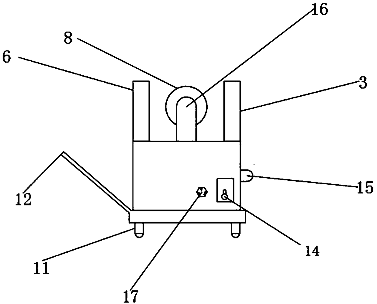
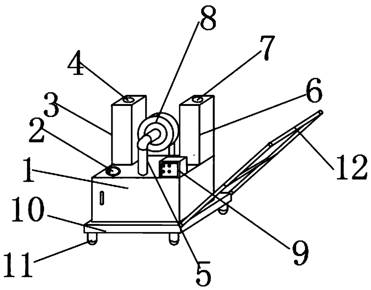
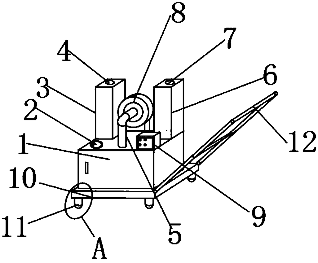
[0018] Such as Figure 1-4 As shown, a hand-push type smoke treatment equipment includes a water storage tank 1. A water filling port 2 is fixedly installed on the outer surface of the upper end of the water storage tank 1, and the upper outer surface of the water storage tank 1 is arranged close to the rear end of the water filling port 2. There is a high-efficiency spray box 3, the upper outer surface of the high-efficiency spray box 3 is provided with an air inlet 4, the upper outer surface of the water storage tank 1 is provided with an inlet pipe 5 on the side close to the high-efficiency spray box 3, and the water storage tank 1 An activated carbon adsorption box 6 is provided on the outer surface of the upper end near the inlet pipe 5, an air outlet 7 is provided on the outer surface of the upper end of the activated carbon adsorption box 6, and an air pump 8 is connected to the rear end of the inlet pipe 5, and the upper end of the water storage tank 1 An electric control box 9 is provided on the outer surface close to the front of the activated carbon adsorption box 6, and the lower end of the water storage tank 1 is provided with a base 10, the lower end of the base 10 is provided with a rolling shaft 11, and one end of the base 10 is connected with a handrail 12 and a rolling shaft 11. A ball 13 is provided on the inner side of the water storage tank 1, a start switch 14 is provided on the outer surface of the rear end of the water storage tank 1, a work prompt light 15 is provided on one side of the water storage tank 1, and the upper outer surface of the water storage tank 1 is close to the rear of the air pump 8. An outlet air pipe 16 is provided at the end, and a power socket 17 is provided on the outer surface of the rear end of the water storage tank 1 close to the start switch 14.
[0019] An air pump 8 is provided between the inlet air pipe 5 and the outlet air pipe 16, a fixing screw is arranged between the air pump 8 and the inlet air pipe 5, and a fixing screw is also arranged between the air pump 8 and the outlet air pipe 16, and the inlet air pipe 5 is pumped through The air pump 8 is fixedly connected with the fixed screw and the air outlet pipe 16; a bearing is arranged between the rolling shaft 11 and the ball 13, the rolling shaft 11 is movably connected with the ball 13 through the bearing, and the inner side of the bearing is coated with a lubricating coating; the high-efficiency spray box 3 and the storage A fixed screw and a water pipe are arranged between the water tank 1. The high-efficiency spray box 3 is fixedly connected to the water storage tank 1 by a fixed screw and a water pipe. A fixed screw is arranged between the activated carbon adsorption tank 6 and the water storage tank 1. The activated carbon adsorption tank 6 It is fixedly connected with the water storage tank 1 by fixing screws; a pipe is provided between the inlet air pipe 5 and the air inlet 4, the inlet air pipe 5 is fixedly connected with the air inlet 4 through the pipe, and a pipe is provided between the outlet air pipe 16 and the air outlet 7 , The air pipe 16 is fixedly connected with the air outlet 7 through the pipeline; a fixing screw is arranged between the water storage tank 1 and the base 10, and the water storage tank 1 is fixedly installed on the base 10 by the fixing screw, and the outer surface of the upper end of the base 10 is provided with threads , The number of threads is several groups, and the threads spread outward from the center of the outer surface of the upper end of the base 10.
[0020] It should be noted that the present invention is a hand-push type smoke treatment equipment. When in use, the user activates the suction pump 8 and the spray head inside the high-efficiency spray box 3 by pressing the start switch 14, and then uses the handrail 12 Push the equipment to an area with dense smoke for smoke treatment. In the process of handling the smoke, you can also know the working status of the equipment through the work prompt light 15. Through the water filling port 2, you can add water or change the water inside the water storage tank 1 to Ensure the efficiency of the smoke treatment process and accelerate the deposition of smoke impurities. Through the internally connected air inlet 4, the inlet air pipe 5, the outlet air pipe 16 and the air outlet 7, air can be introduced into the treatment process, speed up the work rate, and improve efficiency. In terms of floor area, the handrail 12, the rolling shaft 11 and the ball 13 can be used to move the equipment, which greatly saves space and indirectly improves the work efficiency of the workshop. The above advantages make the hand-push smoke processor greatly surpass the traditional use prospects Smoke treatment equipment.
[0021] The basic principles and main features and advantages of the present invention have been shown and described above. Those skilled in the industry should understand that the present invention is not limited by the foregoing embodiments. The foregoing embodiments and descriptions only illustrate the principles of the present invention. Without departing from the spirit and scope of the present invention, the present invention will have Various changes and improvements, these changes and improvements all fall within the scope of the claimed invention. The scope of protection claimed by the present invention is defined by the appended claims and their equivalents.

PUM

no PUM

Description & Claims & Application Information

We can also present the details of the Description, Claims and Application information to help users get a comprehensive understanding of the technical details of the patent, such as background art, summary of invention, brief description of drawings, description of embodiments, and other original content. On the other hand, users can also determine the specific scope of protection of the technology through the list of claims; as well as understand the changes in the life cycle of the technology with the presentation of the patent timeline. Login to view more.

Similar technology patents

Defrosting method of air source heat pump water heater

ActiveCN106152643AProtect device securitygood effect
Owner:江苏鑫昊空调设备有限公司

Novel spraying agent for reducing indoor haze, and application thereof

InactiveCN104910866AExtensive sources of materialsgood effect
Owner:GUANGDONG UNIV OF TECH

Classification and recommendation of technical efficacy words

Why Eureka
Try Eureka