
An industrial dust collector

A dust collector and dust technology, which is applied in the field of industrial dust collectors, can solve problems such as poor dust removal effect and large noise pollution, and achieve the effects of smooth confluence, reduced waste, and reduced noise pollution

Active Publication Date: 2020-11-27
ANHUI XINKUN PURIFICATION EQUIP
View PDF11 Cites 0 Cited by
  • Summary
  • Abstract
  • Description
  • Claims
  • Application Information

AI Technical Summary

Problems solved by technology

However, the existing dust collectors for industrial dust can only deal with a single layer of fugitive dust, and the dust removal effect is not good, and the dust removal process will also generate relatively large noise pollution

Method used


Image

  • An industrial dust collector
  • An industrial dust collector
  • An industrial dust collector

Examples


Embodiment 1

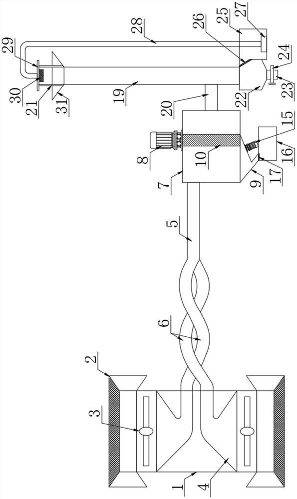
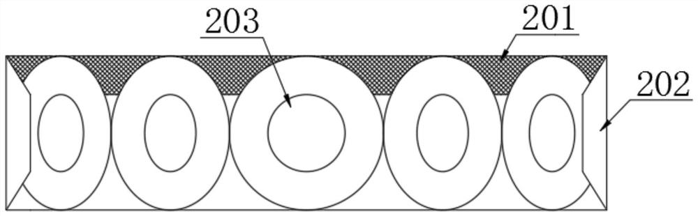
[0027] The present invention provides such Figure 1-5 The shown industrial dust collector includes a connecting sleeve 1, and both ends of the connecting sleeve 1 are provided with an air inlet mechanism 2, and the air inlet mechanism 2 includes a first flared groove 201 and a second flared groove. The first flared groove 201 and the second flared groove 202 are vertically arranged, and the shrinking ends of the first flared groove 201 and the second flared groove 202 are equipped with an air inlet 203, The connection between the connecting sleeve 1 and the air inlet mechanism 2 is provided with a turbofan 3, and the bottom of the turbofan 3 is provided with an air-introduction chamber 4, and the air-introduction chamber 4 is arranged inside the connecting sleeve 1, and the connecting sleeve One side of cylinder 1 is provided with a main pipe 5, and a spiral connecting pipe 6 is arranged between the said air-inducing chamber 4 and the main pipe 5, and the two are connected th...

Embodiment 2

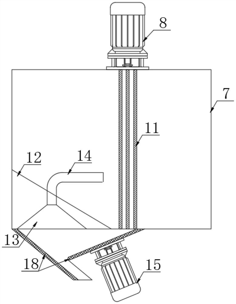
[0030]Further, in the technical solution of Example 1, the inner wall of the dust discharge port 9 is provided with a drain plate 18, and the number of the drain plate 18 is two, and they are respectively arranged on the left and right sides of the dust discharge port 9. On the inclined side wall, the length of the flow guide plate 18 of the left side wall is greater than the length of the flow guide plate 18 of the right side wall, so that the part wind in the dust removal box forms a return air passage under the cooperation of the left and right two flow guide plates 18, so that The guided return wind flows into the return air slot 13, and is returned to the dust removal box by the return air pipe 14 at the end of the return air slot 13, so as to avoid the problem of dust flying caused by the wind flowing into the dust collection box 16.

[0031] Further, in the technical solution of Example 1, the inner wall of the main pipe 5 is provided with a spiral air guide plate 32, wh...


PUM


Abstract

The invention discloses an industrial dust collector, which comprises a connecting sleeve. Both ends of the connecting sleeve are provided with an air inlet mechanism. The air inlet mechanism consists of a first flared groove and a second flared groove. The first flaring groove and the second flaring groove are vertically arranged, and the shrinking ends of the first flaring groove and the second flaring groove are equipped with an air inlet, and the connecting sleeve is connected with the air inlet mechanism A turbofan is arranged at the place, and an air induction chamber is arranged at the bottom of the turbofan. The present invention uses two upper and lower air intake mechanisms to suck the industrial dust in the working environment into the respective corresponding air induction chambers under the action of the turbofan, and then flow into them through the single pipe drainage of the spiral connecting pipes connected respectively. Into the main pipe with the spiral air-inducing plate, it can realize the treatment of the dust on the upper and lower layers, and at the same time, it can make the confluence of the dust-containing air more stable, and greatly reduce the noise pollution generated during the confluence process.

Description

technical field [0001] The invention relates to the field of industrial dust removal equipment, in particular to an industrial dust collector. Background technique [0002] In recent years, with the rapid development of industry, industrial pollution has become more and more serious. A lot of dust will be generated in industrial production, and these dust will enter the air and be discharged into the air, resulting in serious air pollution, and serious fog will appear In the case of haze, such air quality will greatly affect people's health. However, the existing dust collectors for industrial dust can only deal with a single layer of fugitive dust, and the dust removal effect is not good, and the dust removal process will also generate relatively large noise pollution. [0003] Therefore, it is necessary to invent a kind of industrial dust collector to solve the above problems. Contents of the invention [0004] The object of the present invention is to provide an indus...

Claims


Application Information

Patent Timeline
Patent Type & Authority Patents(China)
IPC IPC(8): B01D50/00
CPCB01D50/60
Inventor 黄平
Owner ANHUI XINKUN PURIFICATION EQUIP
Features
  • Generate Ideas
  • Intellectual Property
  • Life Sciences
  • Materials
  • Tech Scout
  • Unparalleled Data Quality
  • Higher Quality Content
  • 60% Fewer Hallucinations
Learn More