
Diversion type support grid and fluidized bed reactor for reactor catalyst bed

A catalyst bed, supporting grid technology, used in chemical instruments and methods, chemical/physical processes, etc., can solve the problems of catalyst leakage, cracking, and easy coking of catalysts, so as to reduce frictional resistance and improve service life. Effect

Active Publication Date: 2018-11-23
SINOPEC ENG +1
View PDF8 Cites 0 Cited by
  • Summary
  • Abstract
  • Description
  • Claims
  • Application Information

AI Technical Summary

Problems solved by technology

[0004] However, there is a prominent problem in the cylindrical support grid in the prior art. When the reactor is working, the catalyst particles are in contact with the inner cylinder grid. Because the gap between the V-shaped wire mesh of the inner cylinder grid is small, the catalyst often will block the gap
Especially in high temperature occasions, the catalyst itself is easy to coke, has poor fluidity, and is more likely to adhere to the surface of the support grid, causing agglomeration
If the coking is serious, the temperature of the corresponding part on the inner cylinder will rise, and under the extrusion of the catalyst, the V-shaped wire mesh of the inner cylinder is likely to be deformed or even broken, causing the catalyst to leak out and affecting the normal operation of the reactor.

Method used


Image

  • Diversion type support grid and fluidized bed reactor for reactor catalyst bed
  • Diversion type support grid and fluidized bed reactor for reactor catalyst bed
  • Diversion type support grid and fluidized bed reactor for reactor catalyst bed

Examples


Embodiment 1

[0062] This embodiment is used to illustrate the diversion type supporting grid of the present invention.

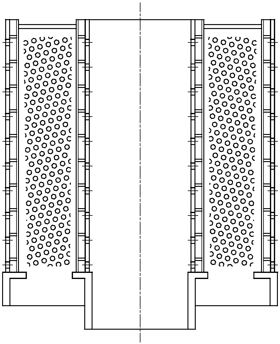
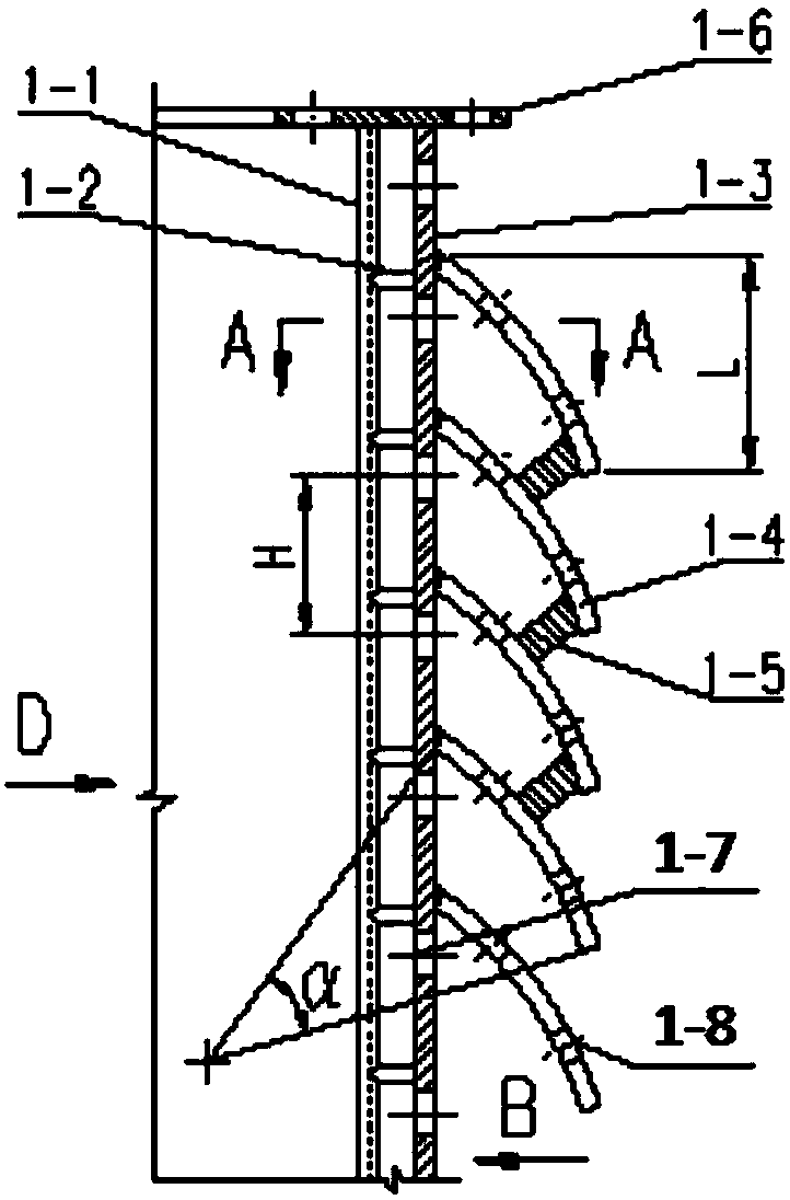
[0063] The diversion support grid is a double-layer cylindrical structure, such as image 3 with Figure 5 As shown, it includes a distribution cylinder 1-1, a support bar 1-2, a contact cylinder 1-3, and a connecting ring plate 1-6 at the end, the distribution cylinder 1-1 and the contact cylinder 1. -3 are arranged in parallel, the support bar 1-2 is located between the distribution cylinder 1-1 and the contact cylinder 1-3, and the contact cylinder 1-3 is adjacent to the catalyst bed 3,

[0064] The contact cylinder 1-3 is provided with evenly distributed multiple circles of channel holes 1-7, and on its side adjacent to the catalyst bed 3, a baffle plate is provided above each circle of channel holes 1-7 1-4. The baffle 1-4 is a circular arc-shaped hood structure, the convex surface of which directly contacts the catalyst bed 3, the concave surface faces the contact cylin...

Embodiment 2

[0070] This embodiment is used to illustrate the diversion type supporting grid of the present invention.

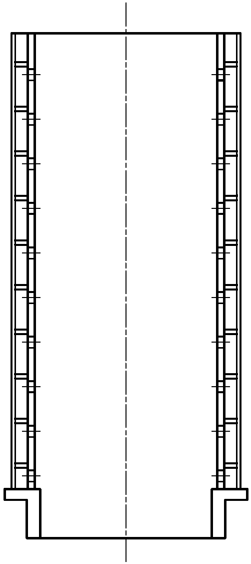
[0071] The diversion support grid is a double-layer cylindrical structure, such as Figure 4 with Image 6 As shown, it includes a distribution cylinder 1-1, a support bar 1-2, a contact cylinder 1-3, and a connecting ring plate 1-6 at the end, the distribution cylinder 1-1 and the contact cylinder 1. -3 are arranged in parallel, the support bar 1-2 is located between the distribution cylinder 1-1 and the contact cylinder 1-3, and the contact cylinder 1-3 is adjacent to the catalyst bed 3,

[0072] The contact cylinder 1-3 is provided with evenly distributed multiple circles of channel holes 1-7, and on its side adjacent to the catalyst bed 3, a baffle plate is provided above each circle of channel holes 1-7 1-4. The baffle 1-4 is a circular arc-shaped hood structure, the convex surface of which directly contacts the catalyst bed 3, the concave surface faces the contact cylin...

Embodiment 3

[0078] This example is used to illustrate the fluidized bed reactor of the present invention.

[0079] Such as Picture 12 with Figure 13 As shown, the fluidized bed reactor includes an inner cylinder grid 1, an outer cylinder grid 2, a shell 4, an inlet pipe 6, a gas distributor 7, an outlet pipe 5, a catalyst feed pipe 9 and a catalyst discharge pipe 10.

[0080] The shell 4, the outer cylindrical grille 2 and the inner cylindrical grille 1 are nested in sequence along the radial direction, and the inner cylindrical grille is supported by a support 8 provided on the inner side wall and / or bottom of the housing 4 1 is connected to the outer cylindrical grille 2, the inlet pipe 6 is arranged at the bottom of the housing 4, the gas distributor 7 is located above the inlet pipe 6, and its axis is aligned with the inner cylindrical grille 1. The axes of the outer cylindrical grid 2 and the shell 4 coincide, the outlet pipe 5 is arranged on the top or side of the shell 4, and the cata...


PUM


Abstract

The invention relates to the field of petrochemical equipment, and provides a diversion type support grid and a fluidized bed reactor for a reactor catalyst bed. The diversion type support grid has adouble-layer cylindrical structure, and comprises a distribution cylinder, supporting strips, a contact cylinder and a connecting annular plate arranged at the end; the distribution cylinder is arranged parallel to the contact cylinder; the supporting strips are positioned between the distribution cylinder and the contact cylinder; the contact cylinder is adjacent to the catalyst bed; the contactcylinder is provided with a plurality of circles of evenly distributed channel holes, and guide plates are arranged on the side face, adjacent to the catalyst bed, of the contact cylinder and above all the circles of channel holes respectively; each guide plate has a circular arc-shaped cover structure, the convex faces of the guide plates are directly contacted with the catalyst bed, and the concave faces of the guide plates face the contact cylinder. The diversion type support grid is provided with the guide plates, so that catalyst particles are effectively prevented from blocking screen mesh gaps or fluid channels of the support grid, the flow of a catalyst is guided, and flow resistance is reduced.

Description

Technical field [0001] The invention relates to the field of petrochemical equipment, in particular to a guide type supporting grid used for a catalyst bed of a reactor, and a fluid bed reactor adopting the guide type supporting grid. Background technique [0002] The catalyst bed support structure of the reactor is generally divided into two types, namely the plane support grid and the cylindrical support grid. These two support structures correspond to axial flow reactor and radial flow reactor respectively. According to whether the catalyst bed is flowing, radial flow reactors can be divided into fixed bed radial flow reactors and fluid bed reactors. Fluidized bed reactors are generally classified as radial flow reactors. [0003] The catalyst bed of the fluidized bed radial flow reactor (hereinafter referred to as the fluidized bed reactor) is generally cylindrical support grid, such as figure 1 Shown. The gas flow direction of this type of reactor is perpendicular to the ax...

Claims


Application Information

Patent Timeline
Patent Type & Authority Applications(China)
IPC IPC(8): B01J8/00B01J8/12
CPCB01J8/003B01J8/006B01J8/12B01J8/125
Inventor 郭雪华许伟段瑞刘震宇夏少青杨良瑾吴海鑫
Owner SINOPEC ENG
Learn More