
A kind of inflation mechanism for flotation machine

A flotation machine and air intake pipe technology, applied in flotation, solid separation, etc., can solve the problems of increased manufacturing cost, difficult processing of the main shaft and bearing body, high operating cost, etc., to improve efficiency, improve aeration effect, and aeration effect Good results

Active Publication Date: 2020-09-08
辽宁招金白云黄金矿业有限公司
View PDF7 Cites 0 Cited by
  • Summary
  • Abstract
  • Description
  • Claims
  • Application Information

AI Technical Summary

Problems solved by technology

When the flotation machine is working, the motor device drives the main shaft impeller to rotate and stir the pulp in the tank, and at the same time, the air filled in the tank is cut into small bubbles, which collide with the mineral particles in the pulp to form mineralized bubbles, and the mineralized bubbles rise to The liquid surface of the slurry forms a foam layer to complete the flotation process. Since the gas filled into the flotation machine has a certain pressure, this pressure is related to the immersion depth of the impeller. Generally, the larger the flotation machine, the greater the immersion depth of the impeller. The greater the pressure required to fill the gas inside the flotation machine, when the existing flotation machine is inflated, the compressed air first enters the inside of the main shaft bearing body, which puts forward high requirements on the sealing effect between the bearing body and the main shaft. The cost will inevitably increase, and it will also affect the follow-up operation cost. Using this inflation method, the processing of the main shaft and bearing body of the flotation machine is very difficult.

Method used


Image

  • A kind of inflation mechanism for flotation machine
  • A kind of inflation mechanism for flotation machine
  • A kind of inflation mechanism for flotation machine

Examples


Embodiment

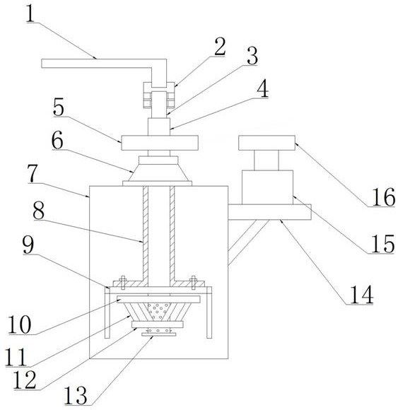
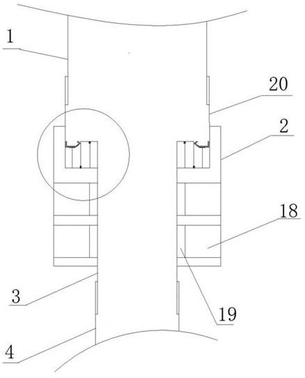
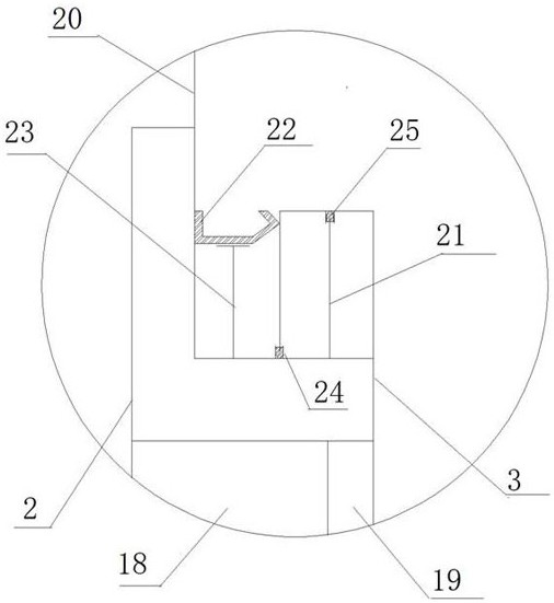
[0022] Example: such as Figure 1 to Figure 6 Shown, a kind of inflation mechanism for flotation machine, comprises casing 7, stirring mechanism, casing 7 right wall outside is provided with first support frame 14, and support frame upper end is provided with motor 15, and motor 15 output shafts are provided with active The belt pulley 16, the stirring mechanism includes a hollow shaft 4, the hollow shaft 4 is vertically arranged, the upper part of the hollow shaft 4 extends out of the box body 7, the upper end of the box body 7 is provided with a bearing body 6, and the bearing body 6 is sleeved on the hollow shaft 4, A driven pulley 5 is arranged above the bearing body 6, and the driven pulley 5 is sleeved on the hollow rotating shaft 4 through a key connection, the middle and lower part of the hollow rotating shaft 4 is arranged in the box body 7, and the lower part of the hollow rotating shaft 4 is provided with a Spoiler cover 9, spoiler cover 9 is set on the hollow rotat...


PUM


Abstract

The invention relates to an air inflation mechanism for a flotation machine. The air inflation mechanism comprises a first air inlet pipe, a sleeve, a second air inlet pipe, an air inlet connecting pipe and a sealing structure, the air inflation mechanism further comprises a box and a hollow rotating shaft, the hollow rotating shaft is vertically arranged, the upper portion of the hollow rotatingshaft extends out of the box, the hollow rotating shaft is sleeved with a driven belt wheel, the lower middle portion of the hollow rotating shaft is arranged in the box, the lower portion of the hollow rotating shaft is provided with a turbulent flow cover, and the turbulent flow cover is arranged on the hollow rotating shaft in a sleeving manner. By means of the air inflation mechanism, a traditional air inflation manner is changed, compressed air can be conveyed into the flotation machine more directly, and the air inflation effect is better.

Description

technical field [0001] The invention relates to the technical field of mining equipment manufacturing, in particular to an inflatable mechanism for a flotation machine. Background technique [0002] The flotation machine is a kind of mineral processing equipment. The flotation machine used in the non-ferrous metal, ferrous metal and non-metallic mineral separation industry usually consists of a motor device, a main shaft part and a tank part. When the flotation machine is working, the motor device drives the main shaft impeller to rotate and stir the pulp in the tank, and at the same time, the air filled in the tank is cut into small bubbles, which collide with the mineral particles in the pulp to form mineralized bubbles, and the mineralized bubbles rise to The liquid surface of the slurry forms a foam layer to complete the flotation process. Since the gas filled into the flotation machine has a certain pressure, this pressure is related to the immersion depth of the impell...

Claims


Application Information

Patent Timeline
Patent Type & Authority Patents(China)
IPC IPC(8): B03D1/16
CPCB03D1/16
Inventor 张保粮
Owner 辽宁招金白云黄金矿业有限公司
Learn More