Cleaning device inside solar energy heat collection pipe

A technology for solar collector tubes and cleaning equipment, which is applied to the field of cleaning equipment inside the solar collector tubes, and can solve the problems of easy movement of the collector tubes and incomplete cleaning.

Active Publication Date: 2018-11-23
杭州全要素科技服务有限公司
View PDF15 Cites 12 Cited by
  • Summary
  • Abstract
  • Description
  • Claims
  • Application Information

AI Technical Summary

Problems solved by technology

[0004] In order to overcome the shortcomings of manual cleaning of the heat collecting tubes, the cleaning is not comprehensive, and the heat collecting tubes are easy to move and affect the cleaning. Therefore, the technical problem of the present invention is to provide a comprehensive cleaning method that can place the heat collecting tubes well, Cleaning equipment inside the solar collector tube without affecting the cleanliness

Method used


Image

  • Cleaning device inside solar energy heat collection pipe
  • Cleaning device inside solar energy heat collection pipe
  • Cleaning device inside solar energy heat collection pipe

Examples


Embodiment 1

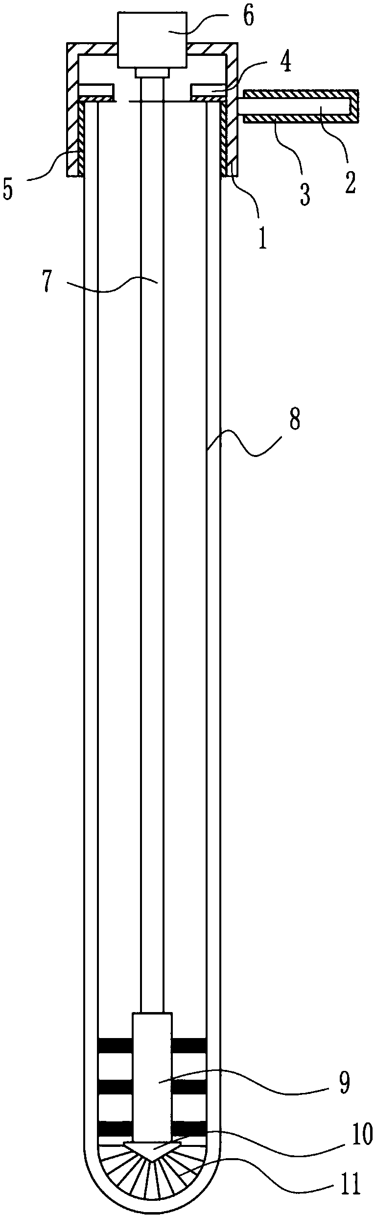
[0020] A kind of internal cleaning equipment of solar heat collecting tube, such as Figure 1-3 As shown, it includes a frame body 1, a handle 2, a rubber sleeve 3, a limit block 4, a rubber plate 5, a motor 6, a rubber rotating rod 7, a roller brush 9, a tapered block 10 and a brush 11. A handle 2 is installed in the middle part of the right side, and a rubber sleeve 3 is arranged on the handle 2. Limiting blocks 4 are installed on the upper left side and the upper right side of the frame body 1. The lower part of the side is equipped with a rubber plate 5, and a motor 6 is embedded in the middle of the top of the frame body 1. The output shaft of the motor 6 is connected to a rubber rotating rod 7 through a coupling. The rubber rotating rod 7 is located under the frame body 1, and the rubber rotating rod 7 A roller brush 9 is installed at the bottom of the rod 7, and a tapered block 10 is installed at the bottom of the roller brush 9, and a hairbrush 11 is installed on the o...

Embodiment 2

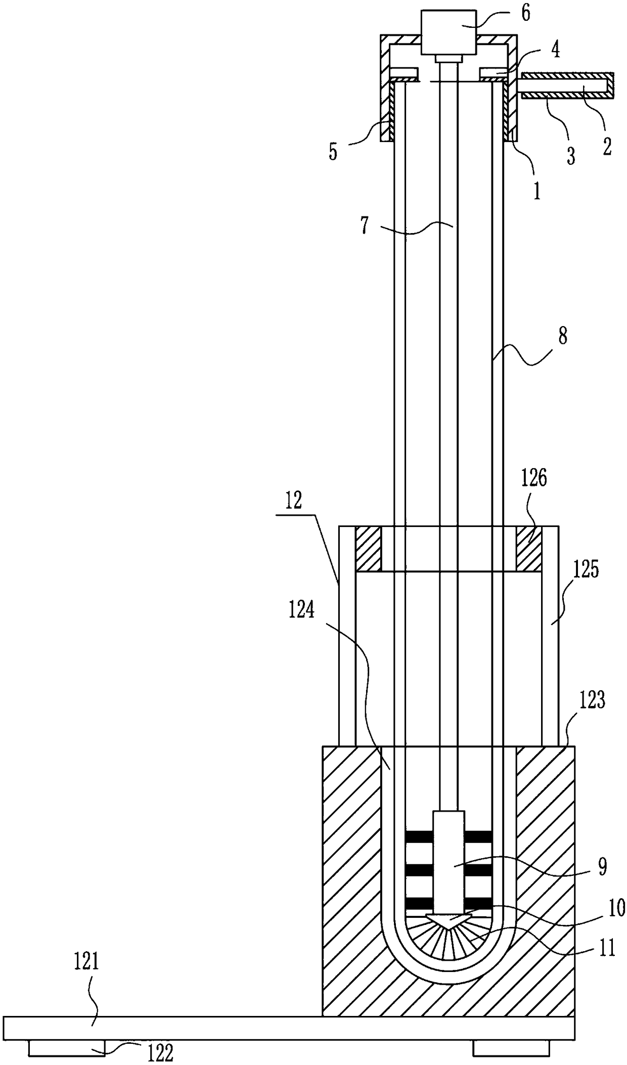
[0022] A kind of internal cleaning equipment of solar heat collecting tube, such as Figure 1-3 As shown, it includes a frame body 1, a handle 2, a rubber sleeve 3, a limit block 4, a rubber plate 5, a motor 6, a rubber rotating rod 7, a roller brush 9, a tapered block 10 and a brush 11. A handle 2 is installed in the middle part of the right side, and a rubber sleeve 3 is arranged on the handle 2. Limiting blocks 4 are installed on the upper left side and the upper right side of the frame body 1. The lower part of the side is equipped with a rubber plate 5, and a motor 6 is embedded in the middle of the top of the frame body 1. The output shaft of the motor 6 is connected to a rubber rotating rod 7 through a coupling. The rubber rotating rod 7 is located under the frame body 1, and the rubber rotating rod 7 A roller brush 9 is installed at the bottom of the rod 7, and a tapered block 10 is installed at the bottom of the roller brush 9, and a hairbrush 11 is installed on the o...

Embodiment 3

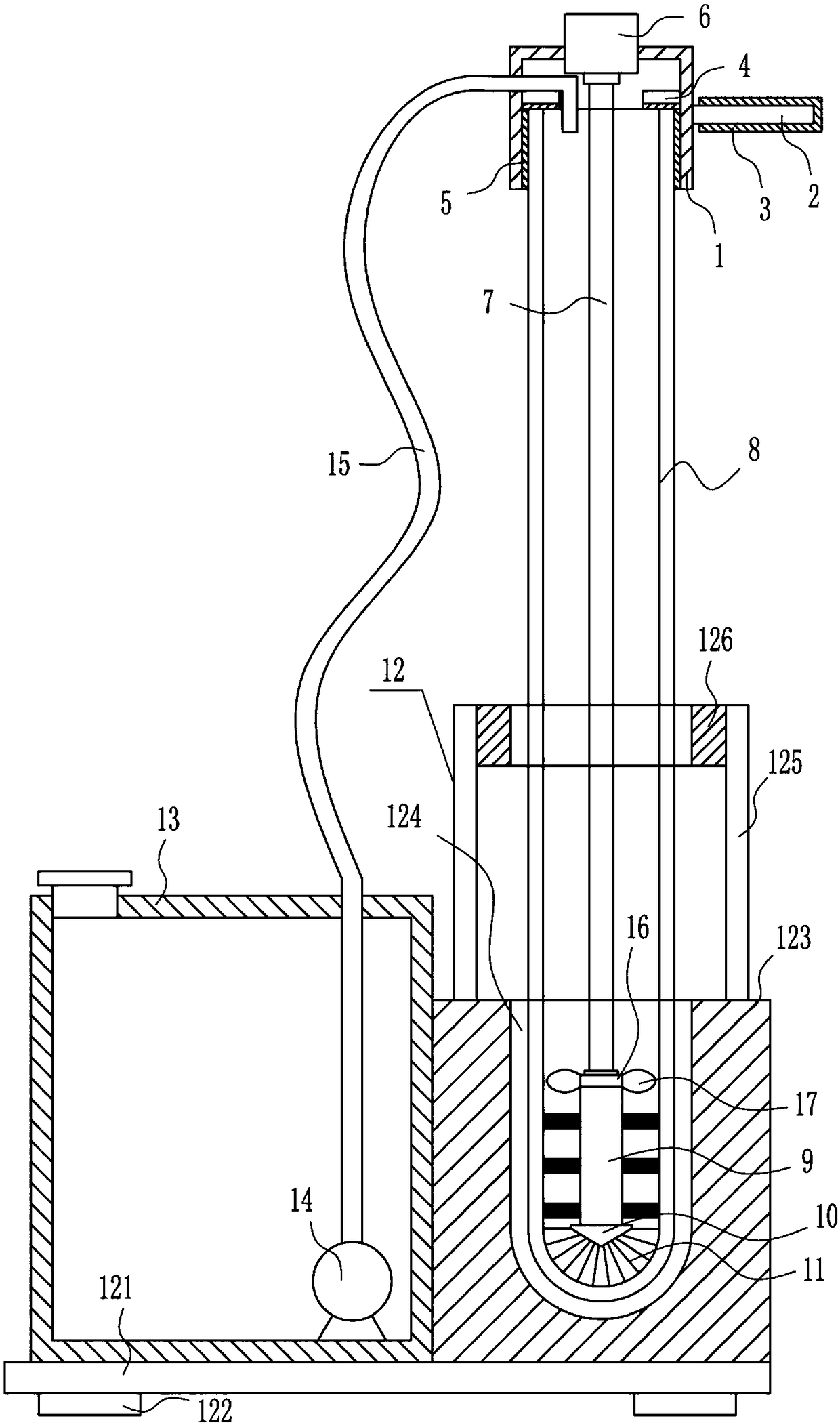
[0025] A kind of internal cleaning equipment of solar heat collecting tube, such as Figure 1-3 As shown, it includes a frame body 1, a handle 2, a rubber sleeve 3, a limit block 4, a rubber plate 5, a motor 6, a rubber rotating rod 7, a roller brush 9, a tapered block 10 and a brush 11. A handle 2 is installed in the middle of the right side, and a rubber sleeve 3 is arranged on the handle 2. Limiting blocks 4 are installed on the upper left side and the upper right side of the frame 1, and the bottom of the limiting block 4 is connected to the left and right sides of the frame 1. The lower part of the side is equipped with a rubber plate 5, and a motor 6 is embedded in the middle of the top of the frame body 1. The output shaft of the motor 6 is connected to a rubber rotating rod 7 through a coupling. The rubber rotating rod 7 is located under the frame body 1, and the rubber rotating rod 7 A roller brush 9 is installed at the bottom of the rod 7, and a tapered block 10 is i...


PUM


Abstract

The invention relates to a cleaning derive, in particular to a cleaning device inside a solar energy heat collection pipe. The cleaning device inside the solar energy heat collection pipe is comprehensive in cleaning, can place the heat collection pipe well without affecting cleaning. According to the technical scheme, the cleaning device inside the solar energy heat collection pipe comprises a frame body, a handle, a rubber sleeve, limiting blocks, rubber plates, a motor, a rubber rotating rod and the like. The handle is installed on the middle part of the right side face outside the frame body, the rubber sleeve is arranged on the handle, the limiting blocks are installed on the upper portions of the left and right side faces in the frame body, and the rubber plates are installed on thebottom portions of the limiting blocks and the left and right side faces in the frame body. According to the cleaning device inside the solar energy heat collection pipe, the heat collection pipe canbe placed steadily through a support device without affecting cleaning; water is not needed to be continuously poured into the heat collection pipe for cleaning by people through a water injection device, convenience and swiftness are achieved, comprehensive cleaning is achieved, the heat collection pipe can be placed well, and the effect of cleaning is not affected.

Description

technical field [0001] The invention relates to a cleaning device, in particular to a cleaning device inside a solar heat collecting tube. Background technique [0002] Solar energy refers to the thermal radiation energy of the sun, the main performance is often said that the sun's rays. In modern times, it is generally used to generate electricity or provide energy for water heaters. [0003] The use of solar energy for a long time requires the removal of the heat collecting tubes for cleaning. Manual cleaning of the heat collecting tubes is not comprehensive, and the heat collecting tubes are easy to move and affect cleaning. Therefore, it is urgent to develop a comprehensive cleaning method that can The heat collector tube is well placed without affecting the cleaning equipment inside the solar heat collector tube. Contents of the invention [0004] In order to overcome the shortcomings of manual cleaning of the heat collecting tubes, the cleaning is not comprehensive...

Claims


Application Information

Patent Timeline
Patent Type & Authority Applications(China)
IPC IPC(8): B08B9/047B08B9/032
CPCB08B9/0321B08B9/047
Inventor 谭令华杨梦
Owner 杭州全要素科技服务有限公司
Why Eureka
Try Eureka