
Stamping die

A technology of stamping dies and templates, which is applied in the field of molds, can solve the problems of inconvenient stamping die product forming, increased unqualified rate of molded products, and larger errors, so as to achieve the effects of improving the qualified rate, ensuring accuracy and stability, and reducing errors

Inactive Publication Date: 2018-11-23
昆山西诺巴精密模具有限公司
View PDF5 Cites 8 Cited by
  • Summary
  • Abstract
  • Description
  • Claims
  • Application Information

AI Technical Summary

Problems solved by technology

[0003] During the use of the existing stamping dies, because there is no fixing device for stamping materials, a slight deviation occurs in the stamping dies when feeding materials. With long-term use, the error becomes larger, which is not convenient for the stamping die products to be formed. As a result, the unqualified rate of finished mold products has increased, so we propose a stamping mold

Method used


Image

  • Stamping die
  • Stamping die

Examples


Embodiment 1

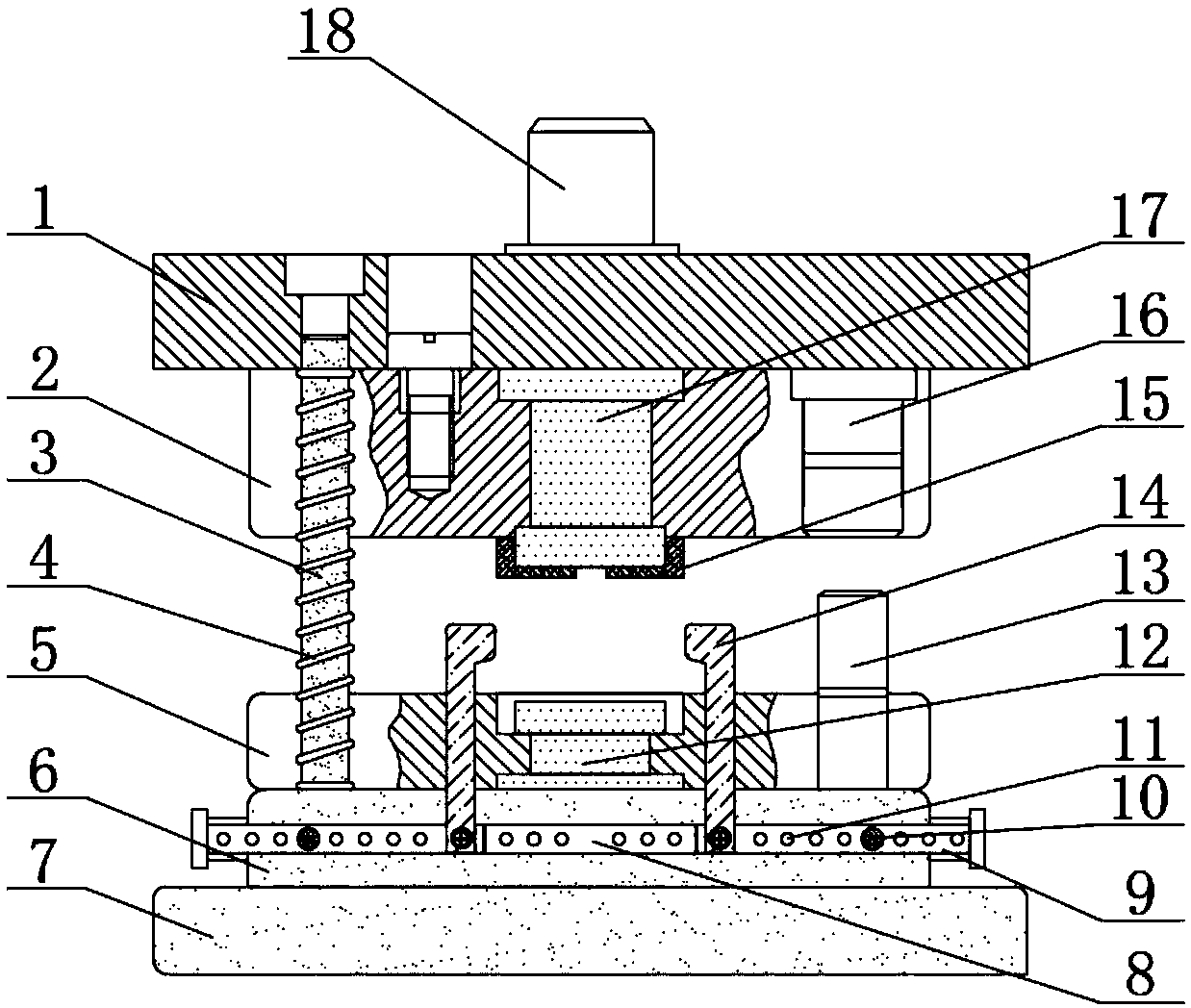
[0019] Embodiment 1: A kind of stamping mold, comprises lower template 7, fixed mold fixed plate 6, fixed mold core 12, upper template 1, pressure plate 2 and movable mold core 17, and described fixed mold fixed plate 6 is fixedly installed on lower template 7 The upper surface of the upper surface of the fixed mold fixed plate 6 is fixedly installed with a stripping plate 5 at the middle position of the upper surface of the fixed mold fixed plate 6. Installed on the lower surface of the upper template 1, a movable mold core 17 is fixedly installed inside the cavity opened at the middle position of the pressure plate 2, and a mold handle 18 is fixedly installed at the middle position of the upper surface of the upper template 1;

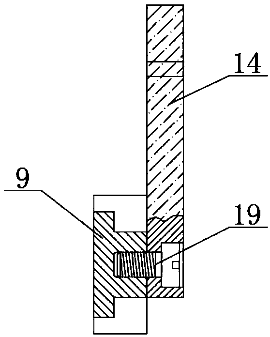
[0020] The front surface of the fixed mold fixed plate 6 is provided with a chute 8, the inside of the chute 8 is equipped with a slide bar 9, and the outer surface of the slide bar 9 is fixedly installed on the side close to the inside of the chute 8...

Embodiment 2

[0024] Embodiment 2: a stamping die, comprising a lower template 7, a fixed mold fixed plate 6, a fixed mold core 12, an upper template 1, a pressing plate 2 and a movable mold core 17, and the fixed mold fixed plate 6 is fixedly installed on the lower template 7 The upper surface of the upper surface of the fixed mold fixed plate 6 is fixedly installed with a stripping plate 5 at the middle position of the upper surface of the fixed mold fixed plate 6. Installed on the lower surface of the upper template 1, a movable mold core 17 is fixedly installed inside the cavity opened at the middle position of the pressure plate 2, and a mold handle 18 is fixedly installed at the middle position of the upper surface of the upper template 1;

[0025] The front surface of the fixed mold fixed plate 6 is provided with a chute 8, the inside of the chute 8 is equipped with a slide bar 9, and the outer surface of the slide bar 9 is fixedly installed on the side close to the inside of the chut...


PUM


Abstract

The invention relates to the technical field of dies, in particular to a stamping die. The stamping die comprises a lower die plate and an upper die plate, wherein the upper surface of the lower template is fixedly provided with a fixed mold fixing plate, a sliding groove is formed in the front surface of the fixed mold fixing plate, sliding rods are arranged in the sliding groove, and limiting clamping plates are fixedly arranged on one sides, close to the interior of the sliding groove, of the outer surfaces of the sliding rods. According to the stamping die, the sliding groove is formed inthe side wall of the fixed mold fixing plate of the mold body, two sets of limiting devices are installed inside the sliding groove, each limiting device is composed of a sliding rod and a limiting clamping plate, and the mounting position of the sliding groove is adjusted through adjusting pin holes and fixing pins which are formed in the outer side walls of the sliding rods, so that the distancebetween the two limiting clamping plates is adjusted, the distance of the two limiting clamping plates is slightly larger than the width of the punching raw materials, the offset of the stamping rawmaterials is controlled within an allowable range, and therefore the error of the stamping size is reduced, and the qualified rate of products is improved.

Description

technical field [0001] The invention relates to a stamping die, which belongs to the technical field of dies. Background technique [0002] Stamping dies are referred to as stamping machines, also known as presses, which are equipment used for pressure processing of materials. Perform cutting, punching, stretching and other processes to form stamping parts. [0003] During the use of the existing stamping dies, because there is no fixing device for stamping materials, a slight deviation occurs in the stamping dies when feeding materials. With long-term use, the error becomes larger, which is not convenient for the stamping die products to be formed. As a result, the unqualified rate of finished mold products has increased, so we propose a stamping mold. Contents of the invention [0004] The purpose of the present invention is to provide a stamping die, which can adjust the distance between two limit clips, so that the distance is slightly larger than the width of the st...

Claims


Application Information

Patent Timeline
Patent Type & Authority Applications(China)
IPC IPC(8): B21D37/10B21D37/12
CPCB21D37/10B21D37/12
Inventor 吕开山
Owner 昆山西诺巴精密模具有限公司
Learn More