
Fixture for assembly of differential pressure transmitters

A differential pressure transmitter and fixture technology, used in manufacturing tools, workpiece clamping devices, etc., can solve the problems of single pressing position, affecting the sealing effect of the upper and lower shells, and shell deflection, and achieve the effect of convenient placement.

Inactive Publication Date: 2018-11-23
HEFEI ZHONGYA SENSOR
View PDF4 Cites 6 Cited by
  • Summary
  • Abstract
  • Description
  • Claims
  • Application Information

AI Technical Summary

Problems solved by technology

[0003] In the production process of the workshop, manual clamping fixtures are generally used in the assembly of differential pressure transmitters. The existing manual clamping fixtures have the problems of small clamping force and single clamping position. During the operation process, due to clamping When the force is small, there will be looseness between the upper and lower shells and the fixture. When connecting, the upper and lower shells will be dislocated, which will make the sealing effect after the connection not good; Compression, generally, is to compress the middle part of the shell, which will cause stress concentration on the surface of the shell, crush the shell, and the pressing position is single, and the moment generated during operation will cause the shell to deflect, thus affecting the up and down The sealing effect of the shell

Method used


Image

  • Fixture for assembly of differential pressure transmitters
  • Fixture for assembly of differential pressure transmitters
  • Fixture for assembly of differential pressure transmitters

Examples


Embodiment Construction

[0025] In order to make the technical means, creative features, goals and effects achieved by the present invention easy to understand, the technical solutions in the embodiments of the present invention will be clearly and completely described below in conjunction with the accompanying drawings in the embodiments of the present invention. Obviously, the The described embodiments are only some, not all, embodiments of the present invention. Based on the embodiments of the present invention, all other embodiments obtained by persons of ordinary skill in the art without creative efforts fall within the protection scope of the present invention.

[0026] In the description of the present invention, it should be noted that the orientation or positional relationship indicated by the terms "vertical", "upper", "lower" and "horizontal" are based on the orientation or positional relationship shown in the drawings, and are only for It is convenient to describe the utility and simplify ...


PUM


Abstract

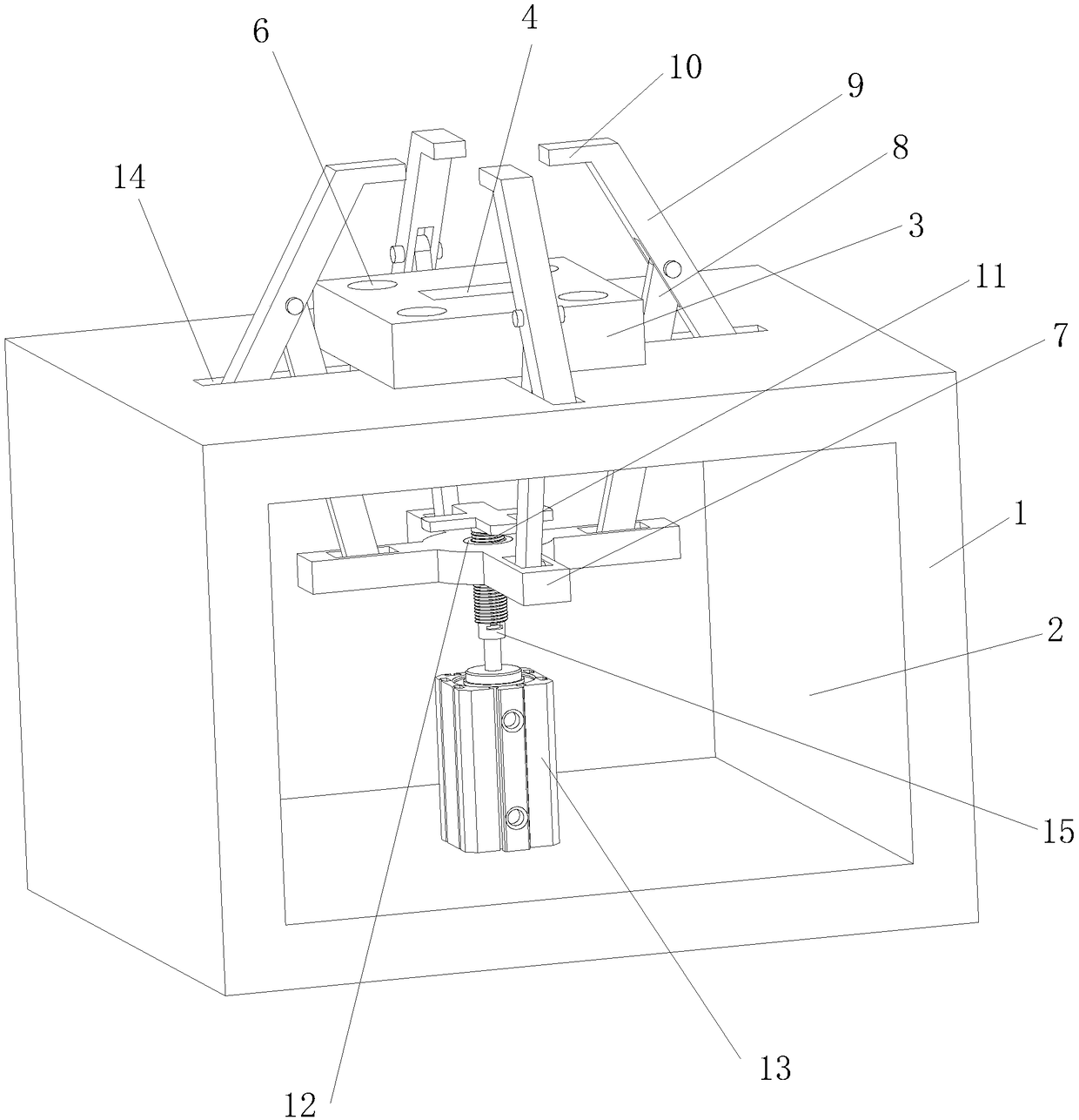
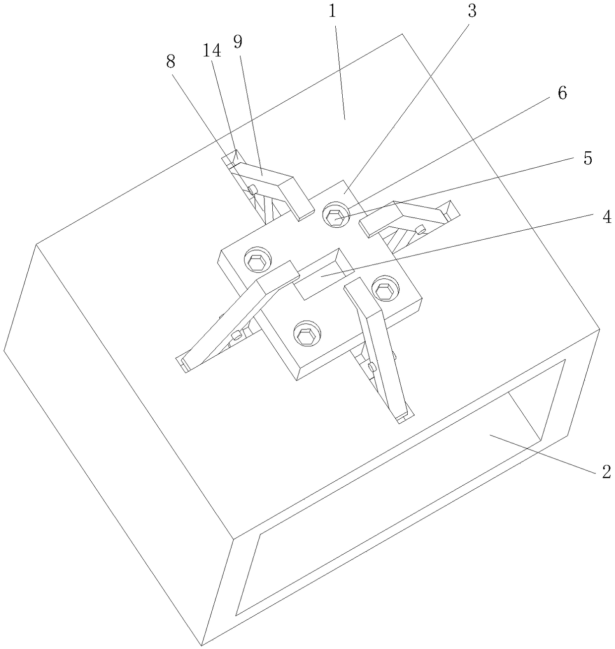
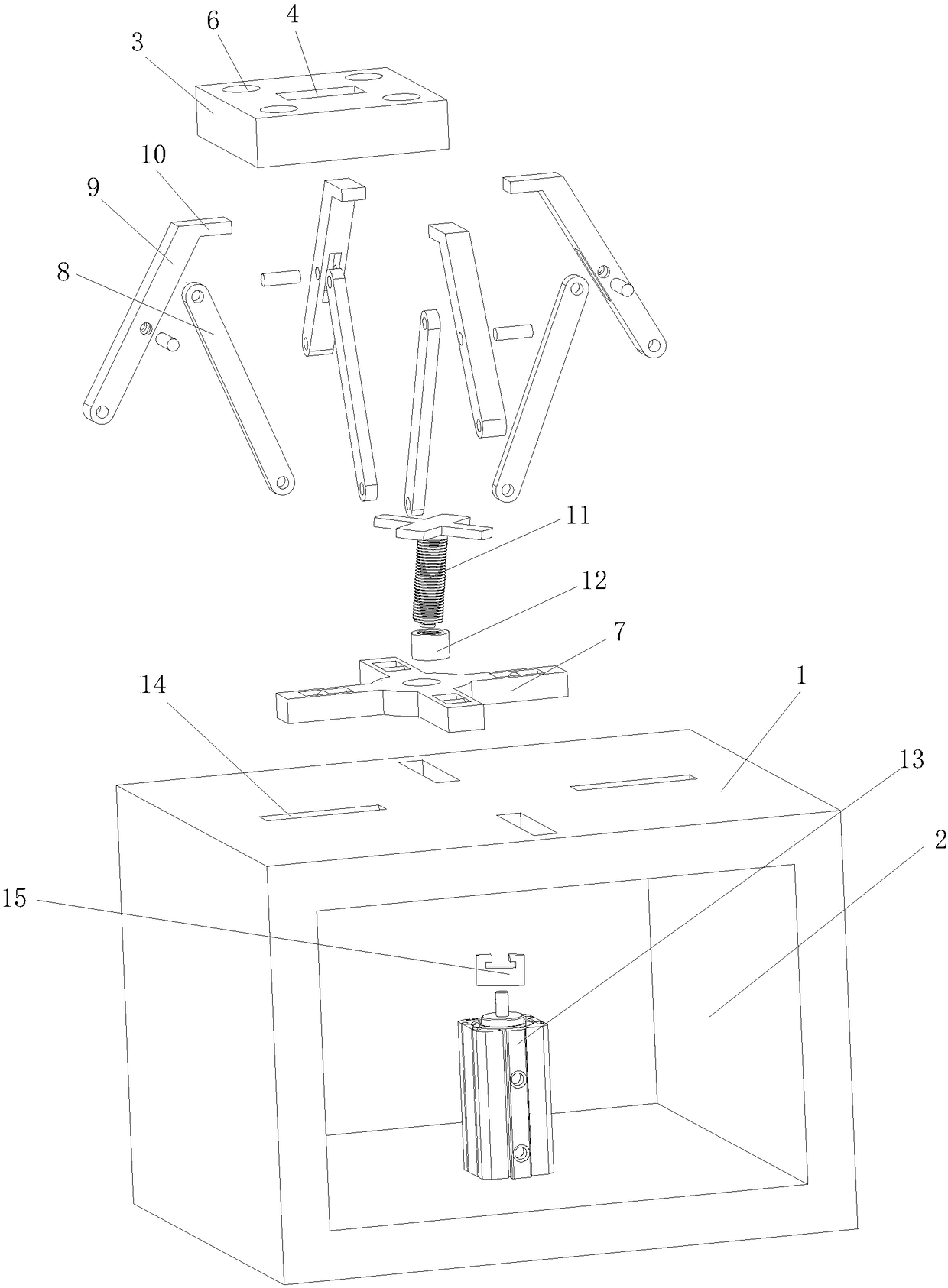
The invention relates to the technical field of processing equipment of differential pressure transmitters, in particular to a fixture for assembly of differential pressure transmitters. The fixture comprises a base, a positioning panel, a driving component, a floating connection support, at least one pair of hinging bars, and presser bars; the positioning panel is connected to the base and is provided with a clearance cavity and four nut mounting cavities; the driving component is fixedly connected to a mounting channel; the driving component drives the floating connection support to move upand down; the hinging bars are arranged correspondingly; the lower ends of the hinging bars are hinged to the floating connection support; the lower ends of the presser bars are hinged to the top of the base. The presser bars, the hinging bars and the floating connection support form a hinge mechanism; the driving component provides driving; therefore, compressing force is better ensured. The presser bars are arranged correspondingly; therefore, compressing force can be applied evenly to a housing, and damage to the housing due to stress concentration is avoided. An adjusting mechanism is provided; therefore, it is ensured that compressing force is enough to compress the housing, with no damage caused to the surface of the housing.

Description

technical field [0001] The invention relates to the technical field of processing equipment for differential pressure transmitters, in particular to a fixture for assembling differential pressure transmitters. Background technique [0002] The differential pressure transmitter is a transmitter that measures the pressure difference between the two ends of the transmitter, and outputs a standard signal (such as ~ 20mA, 0 ~ 5V). Differential pressure transmitters are different from ordinary pressure transmitters in that they all have two pressure ports. Differential pressure transmitters are generally divided into positive pressure ends and negative pressure ends. The pressure at the end should be greater than the pressure at the negative pressure section to be measured. [0003] In the production process of the workshop, manual clamping fixtures are generally used in the assembly of differential pressure transmitters. The existing manual clamping fixtures have the problems of...

Claims


Application Information

Patent Timeline
IPC IPC(8): B25B11/02
Inventor 王武龚庆生虞涛
Owner HEFEI ZHONGYA SENSOR
Features
  • Generate Ideas
  • Intellectual Property
  • Life Sciences
  • Materials
  • Tech Scout
  • Unparalleled Data Quality
  • Higher Quality Content
  • 60% Fewer Hallucinations
Learn More