Discharging system for mechanical equipment

A mechanical equipment and material cutting technology, which is applied in the direction of unloading devices, clay preparation devices, chemical instruments and methods, etc., can solve problems such as easy solidification in the feeding port, inconvenient material dredging, and affecting the normal operation of equipment

Active Publication Date: 2018-11-23
福建省兴岩建筑科技有限公司
View PDF9 Cites 5 Cited by
  • Summary
  • Abstract
  • Description
  • Claims
  • Application Information

AI Technical Summary

Problems solved by technology

[0002] In the process of building construction, it is necessary to use specific mechanical equipment to mix cement, such as cement mixers. When large cement mixers are in use, a large amount of cement and other materials need to be dumped into the mixer. However, due to the large amount of materials and the types of materials Because of different shapes and different humidity, these materials are easy to block in the feed inlet, but ordinary cement mixers are not convenient to dredge the materials, so that the materials are always blocked in the feed inlet, which is not conducive to equipment feeding, and is easy to solidify in the feed inlet. In the feed port, it will affect the normal operation of the equipment, which is not conducive to people's use, so we propose a feeding system for mechanical equipment to solve the above problems

Method used


Image

  • Discharging system for mechanical equipment
  • Discharging system for mechanical equipment
  • Discharging system for mechanical equipment

Examples


Embodiment

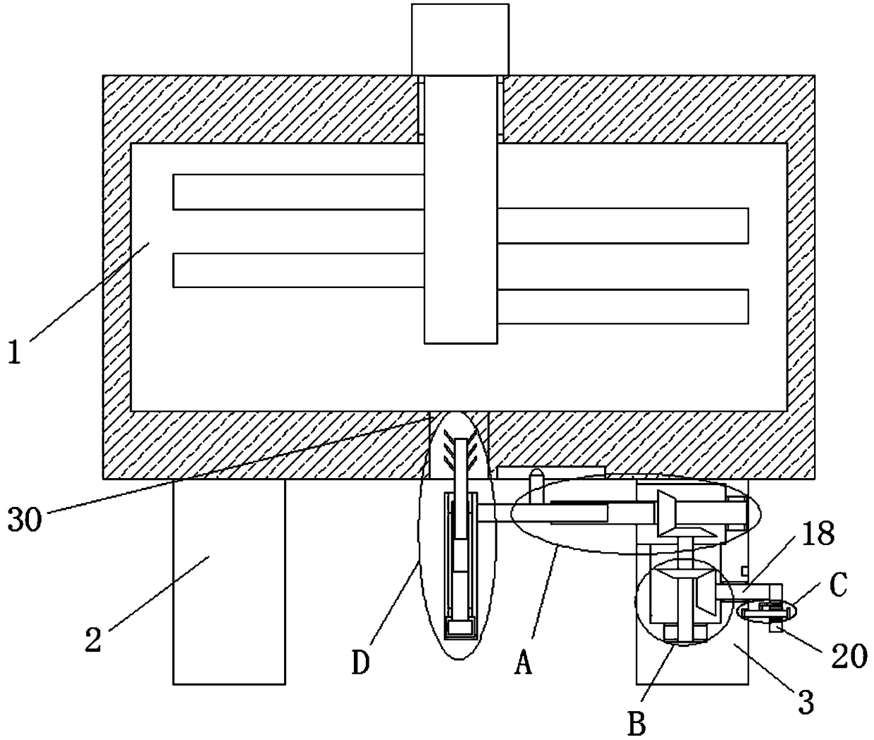
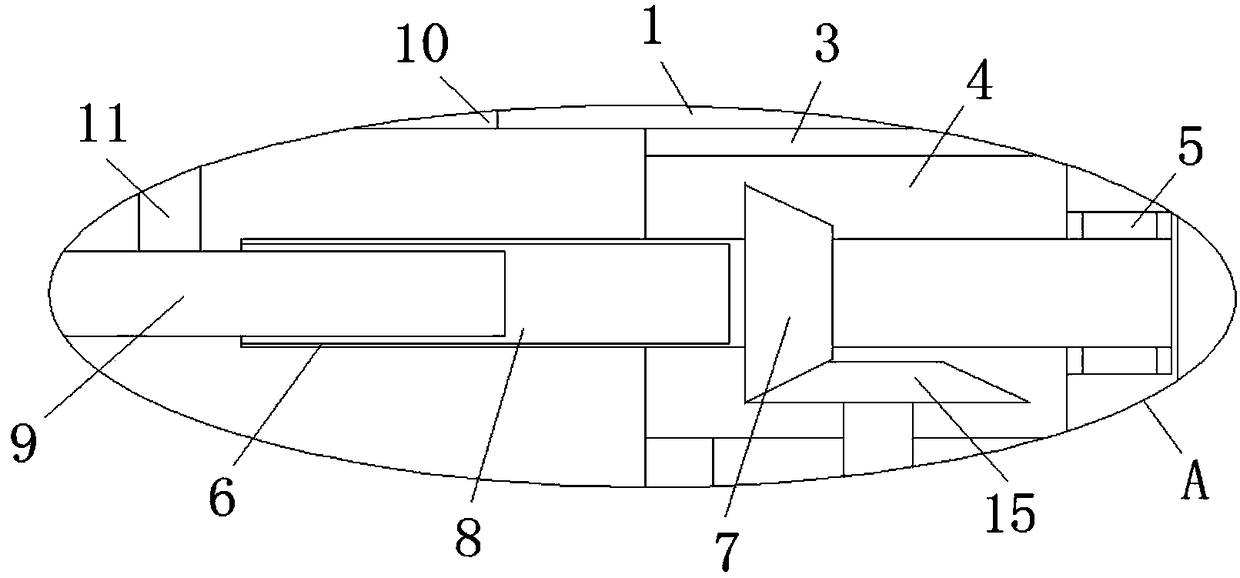
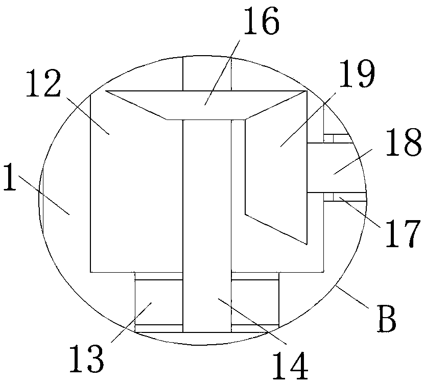
[0026] refer to Figure 1-5In this embodiment, a cutting system for mechanical equipment is proposed, including a mixer 1, a first support column 2 and a second support column 3 are fixedly installed at the bottom of the mixer 1, and the second support column 3 is close to the first support One side of the column 2 is provided with a limiting groove 4, and a first rotating groove 5 is provided on the inner wall of one side of the limiting groove 4, and the same rotating column 6 is installed in the first rotating groove 5 and the limiting groove 4 for rotation. The outer fixed sleeve of the column 6 is provided with a first bevel gear 7, and the end of the rotating column 6 close to the first support column 2 is provided with a first threaded groove 8, and the first threaded groove 8 is internally threaded with a first screw rod 9 , the bottom of the mixer 1 is provided with a first chute 10, the top of the first screw 9 is fixedly installed with a first slider 11, and the fir...


PUM


Abstract

The invention discloses a discharging system for mechanical equipment. The discharging system comprises a mixer, the bottom of the mixer is fixedly provided with a first supporting pillar and a secondsupporting pillar, and the side, close to the first supporting pillar, of the second supporting pillar is provided with a limiting slot. The inner wall of one side of the limiting slot is provided with a first rotating slot, and the first rotating slot and the limiting slot are internally and rotatably provided with the same rotating pillar. The outer side of the rotating pillar is fixedly sleeved with a first conical gear, and the end, close to the first supporting pillar, of the rotating pillar is provided with a first threaded groove. The discharging system is high in practical performance, simple in structure and convenient to operate, and a push plate can push a material in the horizontal direction rapidly and conveniently; and meanwhile, the push plate can also push the material inthe vertical direction rapidly and conveniently, dredging of the blocking material is realized, a discharging opening can perform discharging conveniently, blocking objects on the discharging openingare dredged comprehensively, and requirements of people are met.

Description

technical field [0001] The invention relates to the technical field of blanking systems, in particular to a blanking system for mechanical equipment. Background technique [0002] In the process of building construction, it is necessary to use specific mechanical equipment to mix cement, such as cement mixers. When large cement mixers are in use, a large amount of cement and other materials need to be dumped into the mixer. However, due to the large amount of materials and the types of materials Because of different shapes and different humidity, these materials are easy to block in the feed inlet, but ordinary cement mixers are not convenient to dredge the materials, so that the materials are always blocked in the feed inlet, which is not conducive to equipment feeding, and is easy to solidify in the feed inlet. In the feed port, it will affect the normal operation of the equipment and is not conducive to people's use. Therefore, we have proposed a feeding system for mechan...

Claims


Application Information

Patent Timeline
Patent Type & Authority Applications(China)
IPC IPC(8): B28C5/16B28C5/08B28C7/16
CPCB28C5/0806B28C5/0856B28C5/16B28C7/162
Inventor 郭文英
Owner 福建省兴岩建筑科技有限公司
Why Eureka
Try Eureka