
Positioning device and using method for zip-top can cover

A positioning device and technology for pop-top cans, which are applied in the direction of transportation and packaging, conveyor objects, etc., and can solve problems such as the inability to position stamped pull rings

Active Publication Date: 2018-11-23
XIAMEN BAOFENG IND CO LTD
View PDF8 Cites 2 Cited by
  • Summary
  • Abstract
  • Description
  • Claims
  • Application Information

AI Technical Summary

Problems solved by technology

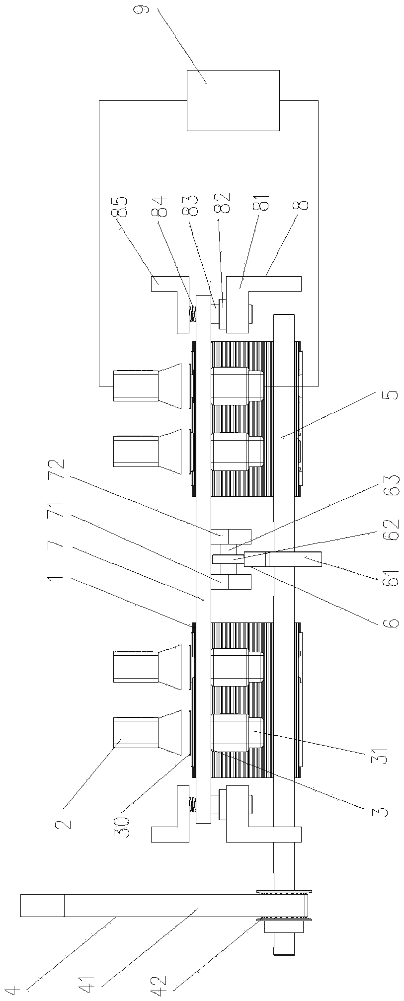
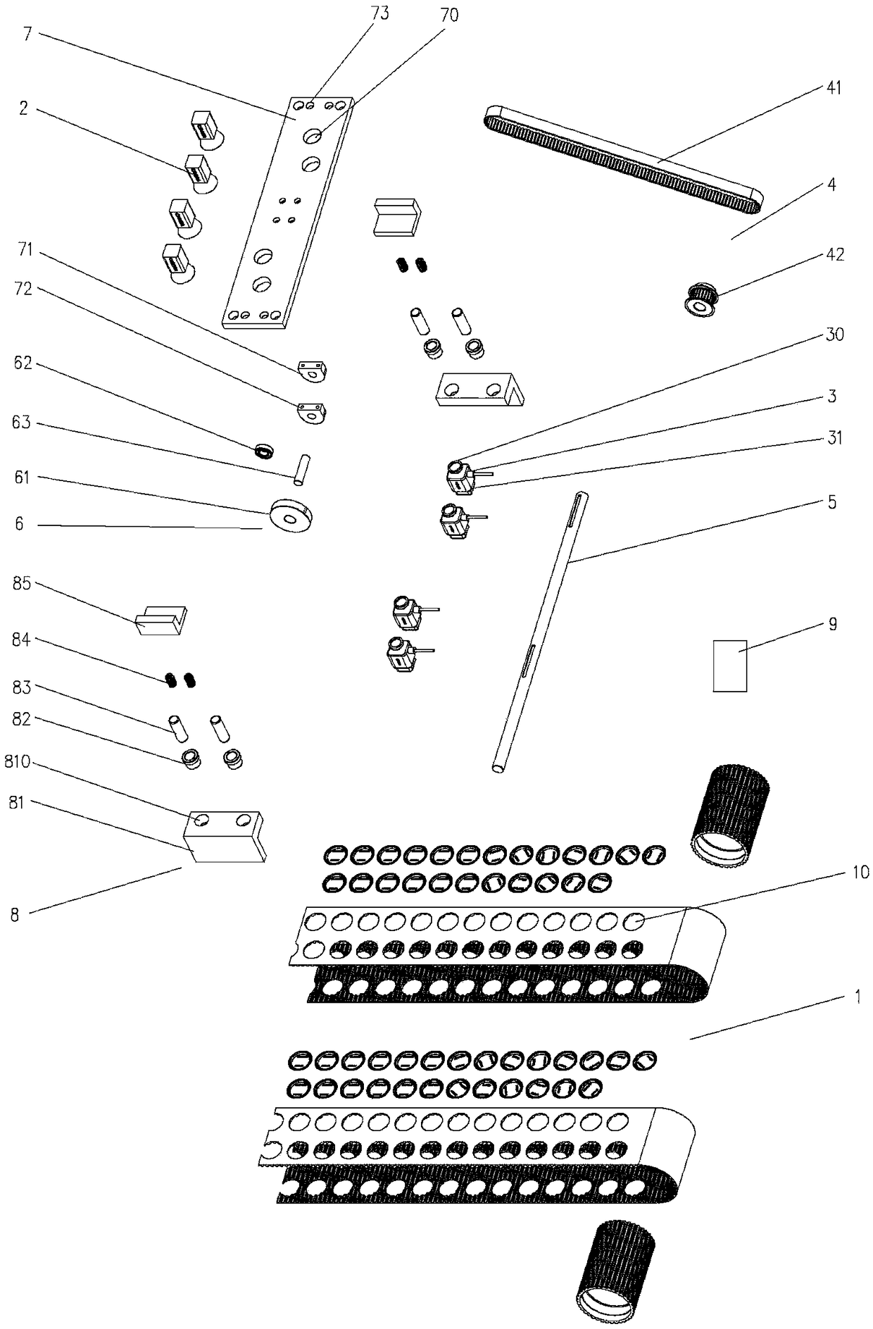
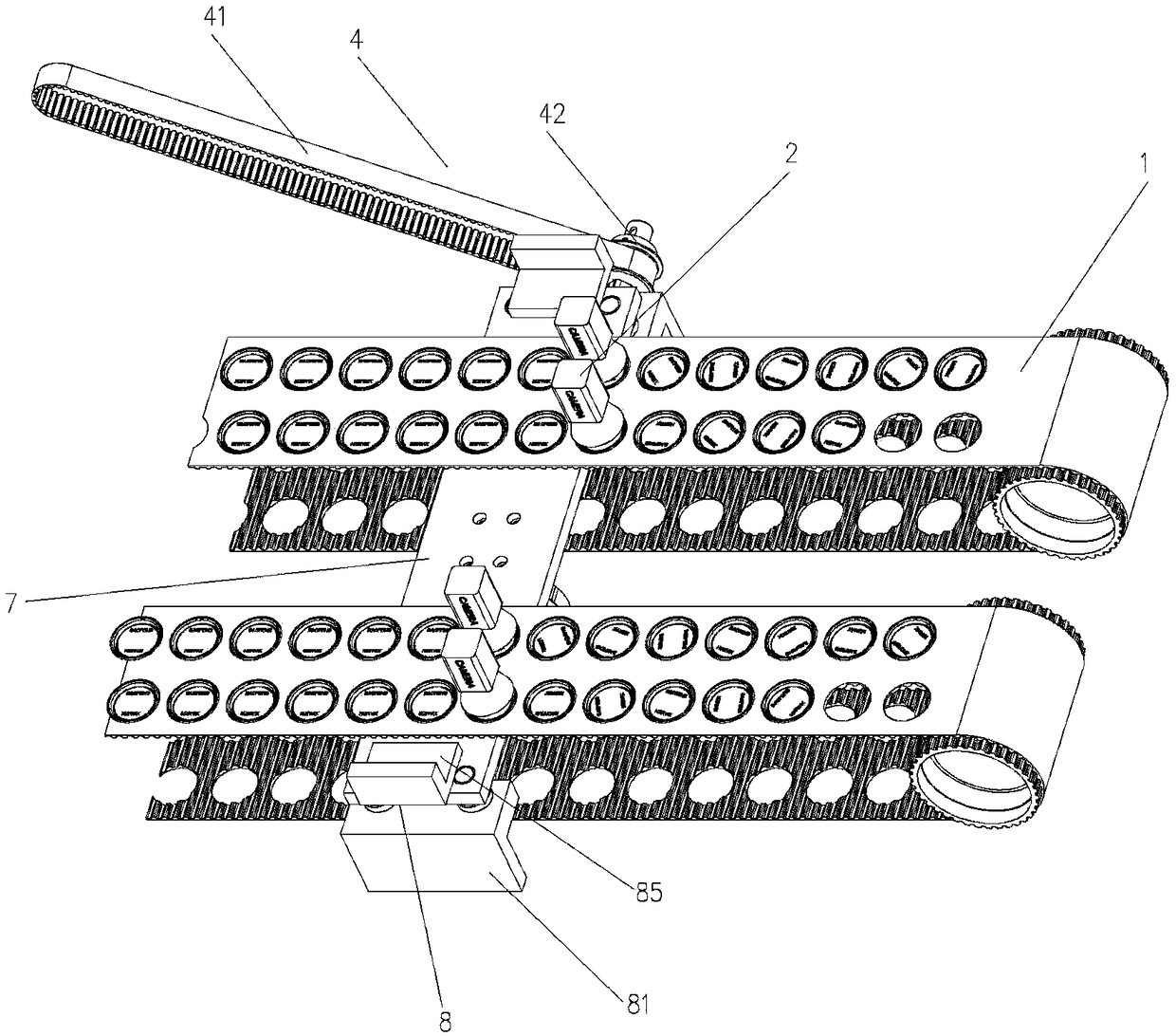
The positioning device for can lids of the present invention is reasonable in structure and novel in design, and can well solve the problem that the direction of the pattern logo on the can lids is messy during the production process, which leads to the inability to locate the stamping tabs; when in use, the synchronization device is driven by a transmission shaft Cam device, the cam device drives the rotary suction mechanism through the fixed plate to reciprocate up and down. When the fixed plate is at the highest point under the action of the cam device, the suction cup on the rotary suction mechanism sucks the can lid, and the controller detects the lid according to the image scanning device. The received pattern identification signal on the can lid controls the rotating suction mechanism to rotate the corresponding angle, so that the pattern identification on the can lid rotates to a predetermined position, and then the suction cup stops sucking the can lid, and the can lid breaks away from the suction cup and is positioned on the belt device to complete the process. The positioning of the required direction, the fixed plate returns to the original position under the action of the reset device; the reset device utilizes the stretching performance of the spring, which can well reset the fixed plate to its original position

Method used


Image

  • Positioning device and using method for zip-top can cover
  • Positioning device and using method for zip-top can cover
  • Positioning device and using method for zip-top can cover

Examples


Embodiment Construction

[0018] In order to make the purpose, technical solutions and advantages of the embodiments of the present invention more clear, the technical solutions in the embodiments of the present invention will be clearly and completely described below in conjunction with the drawings in the embodiments of the present invention.

[0019] Embodiments of the present invention are described in detail below, and examples of the embodiments are shown in the drawings, wherein the same or similar reference numerals denote the same or similar elements or elements having the same or similar functions throughout. The embodiments described below by referring to the figures are exemplary and are intended to explain the present invention and should not be construed as limiting the present invention.

[0020] Such as figure 1 with figure 2 As shown, the positioning device for pop can lids of the present invention includes a belt device 1, an image scanning device 2, a rotating suction mechanism 3, ...


PUM


Abstract

The invention discloses a positioning device for a zip-top can cover. The positioning device comprises a belt device, image scanning devices, rotating sucking mechanisms, a synchronizing device, a transmission shaft, a cam device, a fixing plate, reset devices and a controller; a plurality of first through holes are formed in the belt device and the belt device is used for placing a zip-top can cover; the fixing plate is arranged below the belt device; the rotating sucking mechanisms are fixedly arranged below the fixing plate, and the rotating sucking mechanisms are used for sucking and rotating the zip-top can cover; the image scanning devices comprises cameras, and the cameras are arranged above the belt devices and used for scanning the pattern mark on the zip-top can cover; the synchronous device drives the cam device through the transmission shaft, and the cam device drives the fixing plate to perform up-and-down reciprocating motion; the image scanning devices and the rotating sucking mechanisms are connected to the controller; and the reset devices are arranged at the two ends of the fixing plate. The invention further provides a system for manufacturing the zip-top can cover and a using method for the positioning device for the zip-top can cover.

Description

technical field [0001] The invention belongs to the technical field of pop can lid production, and in particular relates to a positioning device and a use method for pop can lids. Background technique [0002] At present, with the development of science and technology, there are more and more applications of cans with pattern logos. In the promotion of beverages or anti-counterfeiting activities, pattern logos are often set on the can lids, which are beautiful and generous, and can also be scanned with mobile phones. It has become a new type of anti-counterfeiting method for claiming prizes. In the production process of can lids, due to the limitation of batch production process, after the pattern logo on the can lid is printed, the direction of the pattern logo on the can lid will be messy during the transportation process, and the next step is to punch the tab When waiting for the production operation, it is often impossible to accurately locate the pattern mark. It can ...

Claims


Application Information

Patent Timeline
IPC IPC(8): B65G47/24B65G47/91
CPCB65G47/24B65G47/915
Inventor 曾伟刚范维海李炳伟陈志雄
Owner XIAMEN BAOFENG IND CO LTD
Learn More