Hydraulic bridge plug setting tool and bridge plug setting method
What is Al technical title?
Al technical title is built by PatSnap Al team. It summarizes the technical point description of the patent document.
A technology of hydraulic fluid and bridge plug, applied in the field of downhole tools in oil and gas fields, can solve the problems of connection, transfer and maintenance, long length, etc., and achieve the effect of convenient maintenance, short length, and efficient setting of bridge plugs
Pending Publication Date: 2018-11-23
JEREH ENERGY SERVICES
View PDF11 Cites 113 Cited by
Summary
Abstract
Description
Claims
Application Information
AI Technical Summary
This helps you quickly interpret patents by identifying the three key elements:
Problems solved by technology
Method used
Benefits of technology
Problems solved by technology
[0002] Fracturing reservoir stimulation technology is more and more widely used in the exploitation of unconventional oil and gas reservoirs. Bridge plug staged fracturing operations have become a common fracturing method in the industry. Setting bridge plugs through hydraulic setting tools is the most conventional method. Lower bridge plug method, but the current hydraulic setting tool has a long length, which is extremely troublesome for on-site connection, transfer, and maintenance. The long length also adds more uncontrollable factors to downhole operations
Method used
Image
Click on the blue label to locate the original text in one second.
Reading with bidirectional positioning of images and text.
Examples
Embodiment Construction
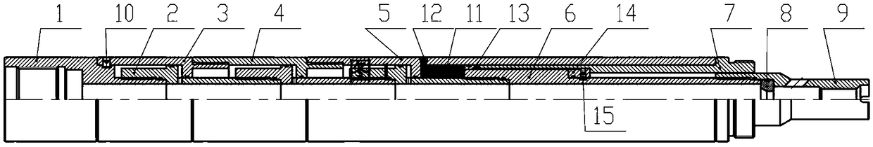
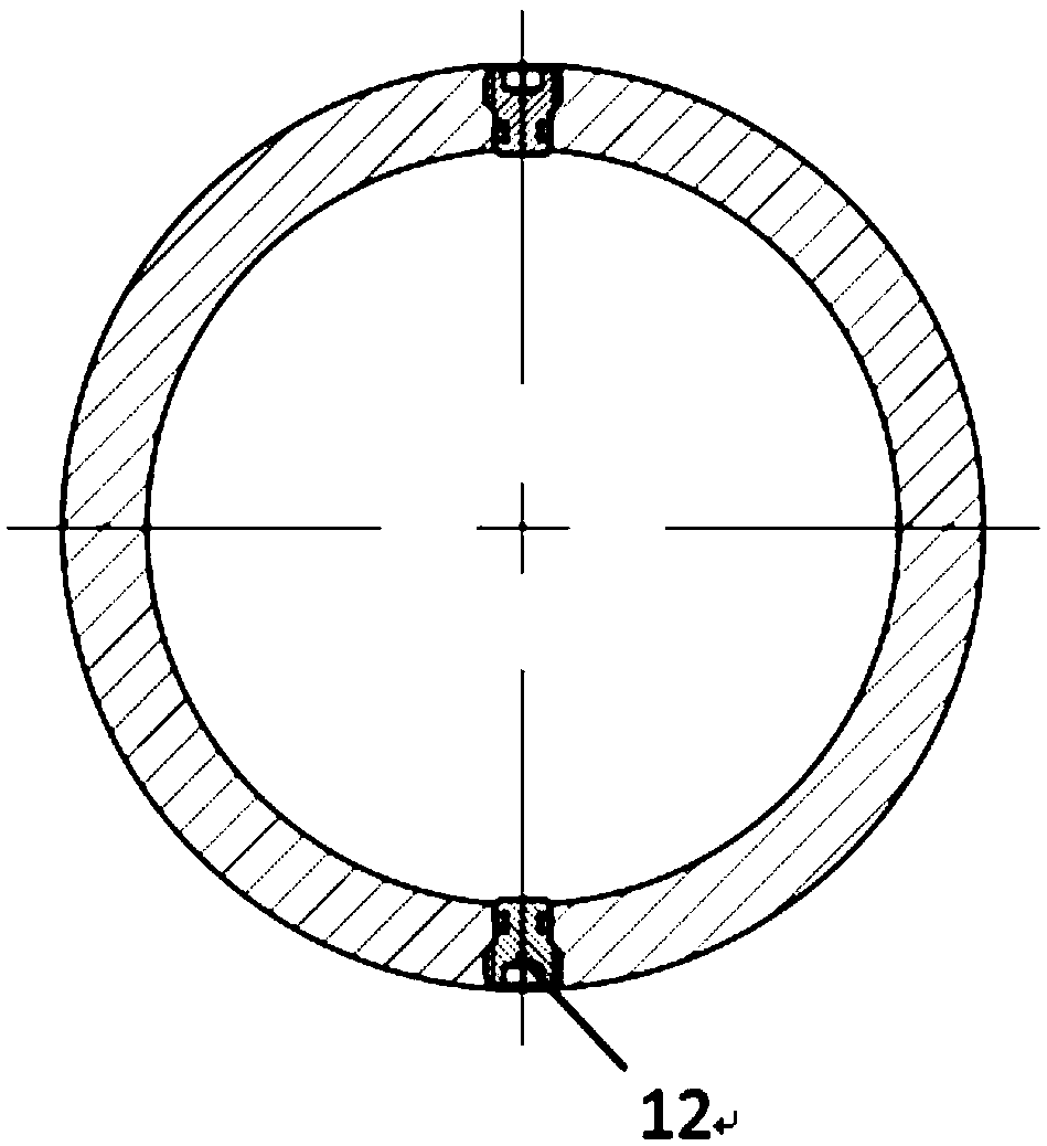
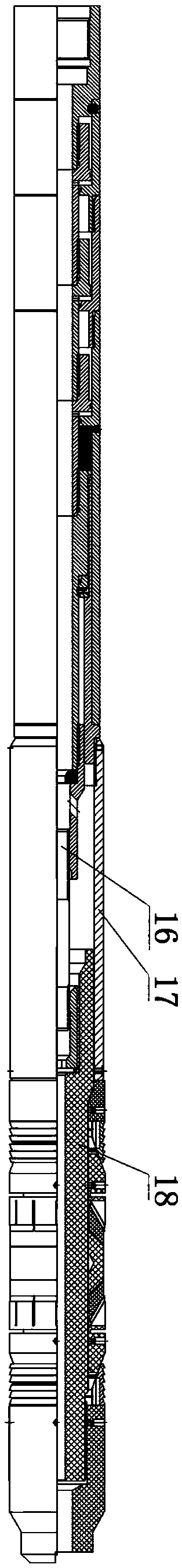
[0027] Examples such as Figures 1 to 3 As shown, the bridge plug hydraulic setting tool of the present invention includes an upper joint 1, a front drive device, a lower center rod 6, a push cylinder connecting sleeve 7, a ball seat 8, a conversion joint 9, a shear pin a10, and a sealing plug 12. Pushing ring 13, composite ring 14, shearing pin b15, upper joint 1 is connected with the front drive device through shear pin a10, push tube connecting sleeve 7 and lower center rod 6 fit up and down on the front drive device, and the front drive Between the device, the lower central rod 6 and the pusher connecting sleeve 7, there is an accommodating sealed cavity for accommodating the liquid. The liquid is an incompressible fluid. 7 can move backwards, when the front drive device compresses and accommodates the sealed cavity, and when the liquid pushes the push ring 13 and the push cylinder connecting sleeve 7 to move backward, an annular ring for accommodating the liquid will be f...
PUM
Abstract
The invention discloses a hydraulic bridge plug setting tool, which comprises an upper joint, a shear pin a, a front drive device, a lower center rod, a push cylinder connection sleeve, a sealing plug, a push ring, a composite ring, a shear pin b, a ball seat, a conversion joint, wherein the upper joint is connected to the front drive device by the shear pin a, the push cylinder connection sleeveand the lower center rod sleeve fitly and snugly the front drive device, and a containing sealed cavity for holding fluid is defined among the front drive device, the lower center rod and the push cylinder connection sleeve; the push ring and the push cylinder connection sleeve are movable backwards, and the containing sealed cavity is formed between the front drive device and the lower center rodafter the movement; the composite ring is connected to the lower center rod through the shear pin b, the sealing plug is arranged on the front drive device, the conversion joint is connected with thelower center rod, and the ball seat is arranged in the inner cavity of the conversion joint. The tool has the advantages of shorter length, convenient use, connection, and maintenance, lower cost, reusability and more efficient bridge plugging. The invention further discloses a bridge plug setting method.
Description
technical field [0001] The invention relates to downhole tools in the field of oil and gas fields, in particular to a bridge plug hydraulic hydraulic setting tool and a bridge plug setting method. Background technique [0002] Fracturing reservoir stimulation technology is more and more widely used in the exploitation of unconventional oil and gas reservoirs. Bridge plug staged fracturing operations have become a common fracturing method in the industry. Setting bridge plugs through hydraulic setting tools is the most conventional method. The method of lowering the bridge plug, but the current hydraulic setting tool has a long length, which is extremely troublesome for on-site connection, transfer, and maintenance. The long length also adds more uncontrollable factors to downhole operations. [0003] For this reason, there is an urgent need for a bridge plug setting tool with short length, convenient on-site connection, transfer and maintenance, and more efficient bridge plu...
Claims
Application Information
Patent Timeline
Application Date:The date an application was filed.
Publication Date:The date a patent or application was officially published.
First Publication Date:The earliest publication date of a patent with the same application number.
Issue Date:Publication date of the patent grant document.
PCT Entry Date:The Entry date of PCT National Phase.
Estimated Expiry Date:The statutory expiry date of a patent right according to the Patent Law, and it is the longest term of protection that the patent right can achieve without the termination of the patent right due to other reasons(Term extension factor has been taken into account ).
Invalid Date:Actual expiry date is based on effective date or publication date of legal transaction data of invalid patent.