Intelligent grouting hole device for tunnel lining trolley

A technology for lining trolleys and grouting holes, applied in tunnel lining, tunnel, shaft lining, etc., can solve the problems of low lining quality, low lining construction efficiency, manual opening and closing of grouting holes, etc., to improve lining quality, The effect of reducing grouting construction accidents and high degree of automation

Pending Publication Date: 2018-11-23
PINGDINGSHAN COAL MINE MACHINERY EQUIP CO LTD
View PDF0 Cites 2 Cited by
  • Summary
  • Abstract
  • Description
  • Claims
  • Application Information

AI Technical Summary

Problems solved by technology

[0003] In order to solve the technical problems of manually opening and closing the grouting holes when using a lining trolley for lining, low lining construction efficiency, and low lining quality, the purpose of this invention is to provide an intelligent grouting hole device for tunnel lining trolleys

Method used


Image

  • Intelligent grouting hole device for tunnel lining trolley
  • Intelligent grouting hole device for tunnel lining trolley

Examples


Embodiment 1

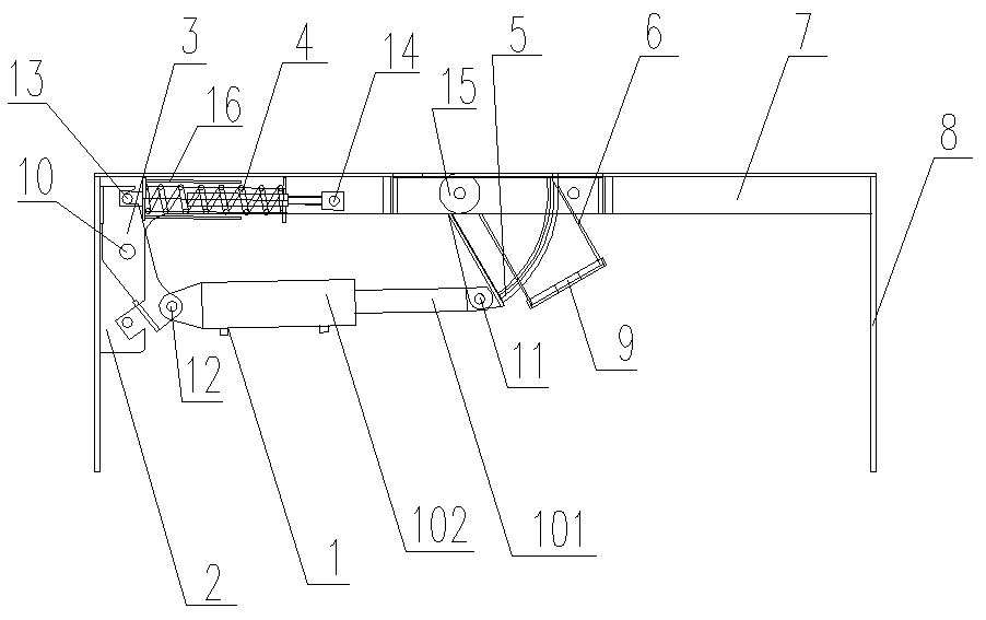
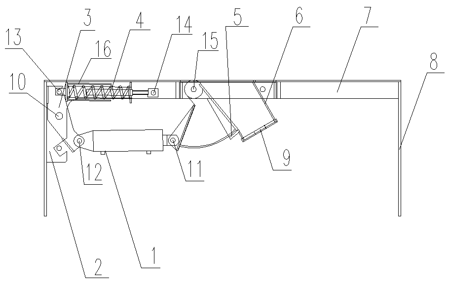
[0013] like Figure 1 to Figure 2 As shown, the intelligent grouting hole device for the tunnel lining trolley includes a horizontal beam 7 and a column 8 arranged at both ends of the beam 7 and vertically connected with the beam 7 .

[0014] A grouting pipe 6 is fixedly arranged on the beam 7, and the grouting pipe 6 is a channel for injecting concrete. The upper part of the grouting pipe 6 is open and the lower part is closed.

[0015] One of the two columns 2 is provided with a fixed lug 2 , and the fixed lug 2 is hinged with a movable lug 3 through a first pin shaft 10 .

[0016] A spring 4 and a hydraulic cylinder 1 are arranged between the movable ear plate 3 and the grouting pipe 6 .

[0017] A baffle 5 is provided between the hydraulic cylinder 1 and the grouting pipe 6 .

[0018] One end of the baffle plate 5 is hinged with the end of the piston rod 101 of the hydraulic cylinder 1 through the second pin 11, and the other end of the baffle plate 5 is passed through t...

Embodiment 2

[0027] like Figure 1 to Figure 2 As shown, the intelligent grouting hole device for the tunnel lining trolley includes a horizontal beam 7 and a column 8 arranged at both ends of the beam 7 and vertically connected with the beam 7 .

[0028] A grouting pipe 6 is fixedly arranged on the beam 7, and the grouting pipe 6 is a channel for injecting concrete. The upper part of the grouting pipe 6 is open and the lower part is closed.

[0029] One of the two columns 2 is provided with a fixed lug 2 , and the fixed lug 2 is hinged with a movable lug 3 through a first pin shaft 10 .

[0030] A spring 4 and a hydraulic cylinder 1 are arranged between the movable ear plate 3 and the grouting pipe 6 .

[0031] A baffle 5 is provided between the hydraulic cylinder 1 and the grouting pipe 6 .

[0032] One end of the baffle plate 5 is hinged with the end of the piston rod 101 of the hydraulic cylinder 1 through the second pin 11, and the other end of the baffle plate 5 is passed through t...

Embodiment 3

[0042] like Figure 1 to Figure 2 As shown, the intelligent grouting hole device for the tunnel lining trolley includes a horizontal beam 7 and a column 8 arranged at both ends of the beam 7 and vertically connected with the beam 7 .

[0043] A grouting pipe 6 is fixedly arranged on the beam 7, and the grouting pipe 6 is a channel for injecting concrete. The upper part of the grouting pipe 6 is open and the lower part is closed.

[0044] One of the two columns 2 is provided with a fixed lug 2 , and the fixed lug 2 is hinged with a movable lug 3 through a first pin shaft 10 .

[0045] A spring 4 and a hydraulic cylinder 1 are arranged between the movable ear plate 3 and the grouting pipe 6 .

[0046] A baffle 5 is provided between the hydraulic cylinder 1 and the grouting pipe 6 .

[0047] One end of the baffle plate 5 is hinged with the end of the piston rod 101 of the hydraulic cylinder 1 through the second pin 11, and the other end of the baffle plate 5 is passed through t...


PUM


Abstract

The invention provides an intelligent grouting hole device for a tunnel lining trolley. The device comprises a cross beam and stand columns, wherein the cross beam is horizontally arranged, and the stand columns are arranged at the two ends of the cross beam and are vertically connected with the cross beam; a grouting pipe is fixedly arranged on the cross beam, the upper part of the grouting pipeis open, and the lower part of the grouting pipe is closed; a slurry outlet is formed in the lower part of the grouting pipe, and a fixed lug plate is arranged on one of the two stand columns; a movable lug plate is hinged to the fixed lug plate through a first pin shaft, a spring and a hydraulic oil cylinder are arranged between the movable lug plate and the grouting pipe, and a baffle is arranged between the hydraulic oil cylinder and the grouting pipe; one end of the baffle is hinged to the end of a piston rod of the hydraulic oil cylinder through a second pin shaft, the other end of the baffle penetrates through the grouting pipe, and the piston rod of the hydraulic oil cylinder drives the baffle to move, so that the baffle blocks or does not block the slurry outlet; a cylinder body ofthe hydraulic oil cylinder is hinged to the movable lug plate through a third pin shaft, one end of the spring is hinged to the movable lug plate through a fourth pin shaft, and the other end of thespring is hinged to the cross beam through a fifth pin shaft.

Description

technical field [0001] The invention relates to the technical field of tunnel construction, in particular to an intelligent grouting hole device for a tunnel lining trolley. Background technique [0002] In recent years, my country's high-speed rail has developed rapidly, and lining trolleys are required for lining high-speed rail tunnels. The pouring material used for the lining is usually cement slurry. During the construction, the workers spend a lot of time and energy to install the concrete delivery pipes. During the grouting, the workers manually open and close the grouting holes. The labor intensity of the workers is high and the construction efficiency is low. If the grouting pressure is too high, the lining concrete may crack, and the quality of the lining cannot be guaranteed, which will affect the progress of the project and increase the construction cost. Contents of the invention [0003] In order to solve the technical problems of manually opening and closin...

Claims


Application Information

Patent Timeline
Patent Type & Authority Applications(China)
IPC IPC(8): E21D11/10E21D11/00
CPCE21D11/003E21D11/10Y02E10/20
Inventor 吴战越许庆伟毛振营王跃功魏延峰常园园张衡张昊
Owner PINGDINGSHAN COAL MINE MACHINERY EQUIP CO LTD
Why Eureka
Try Eureka