
Self-powered magneto-rheological damping device

A damping device and magneto-rheological technology, applied in the direction of shock absorbers, spring/shock absorber functional characteristics, shock absorbers, etc., can solve the problem that the damper cannot provide damping force, the adjustable range of damping force is narrow, and the magnetic flow Problems such as large amount of variable fluid are used to improve the time lag problem, increase the damping adjustment range, and realize the effect of energy recovery

Active Publication Date: 2018-11-23
SHANDONG UNIV
View PDF7 Cites 13 Cited by
  • Summary
  • Abstract
  • Description
  • Claims
  • Application Information

AI Technical Summary

Problems solved by technology

However, the magnetorheological damper that is more commonly studied at present belongs to the piston pore flow mode. This magnetorheological damper requires a large amount of magnetorheological fluid, has a low utilization rate, and is prone to sedimentation and clogging.
At the same time, the adjustable range of the damping force is narrow, and the damper cannot provide an appropriate damping force when the external environment excitation is small

Method used


Image

  • Self-powered magneto-rheological damping device
  • Self-powered magneto-rheological damping device
  • Self-powered magneto-rheological damping device

Examples


Embodiment Construction

[0034]It should be pointed out that the following detailed description is exemplary and intended to provide further explanation to the present application. Unless defined otherwise, all technical and scientific terms used herein have the same meaning as commonly understood by one of ordinary skill in the art to which this application belongs.

[0035] It should be noted that the terminology used here is only for describing specific implementations, and is not intended to limit the exemplary implementations according to the present application. As used herein, unless the context clearly dictates otherwise, the singular is intended to include the plural, and it should also be understood that when the terms "comprising" and / or "comprising" are used in this specification, they mean There are features, steps, operations, means, components and / or combinations thereof;

[0036] For the convenience of description, if the words "up", "down", "left" and "right" appear in the present in...


PUM


Abstract

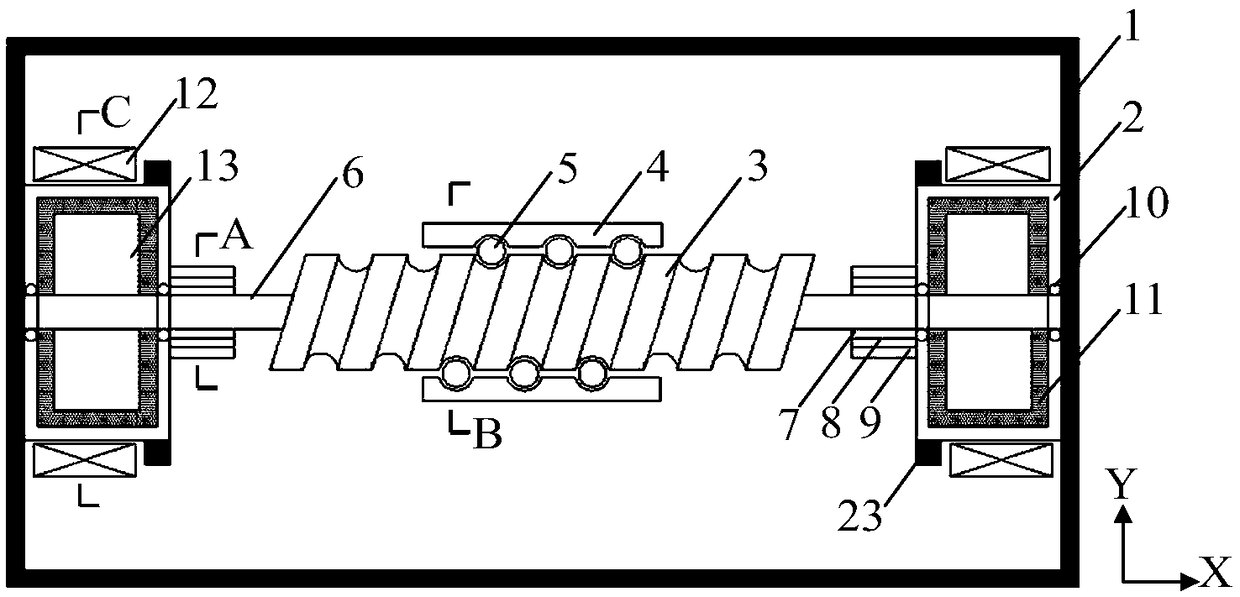
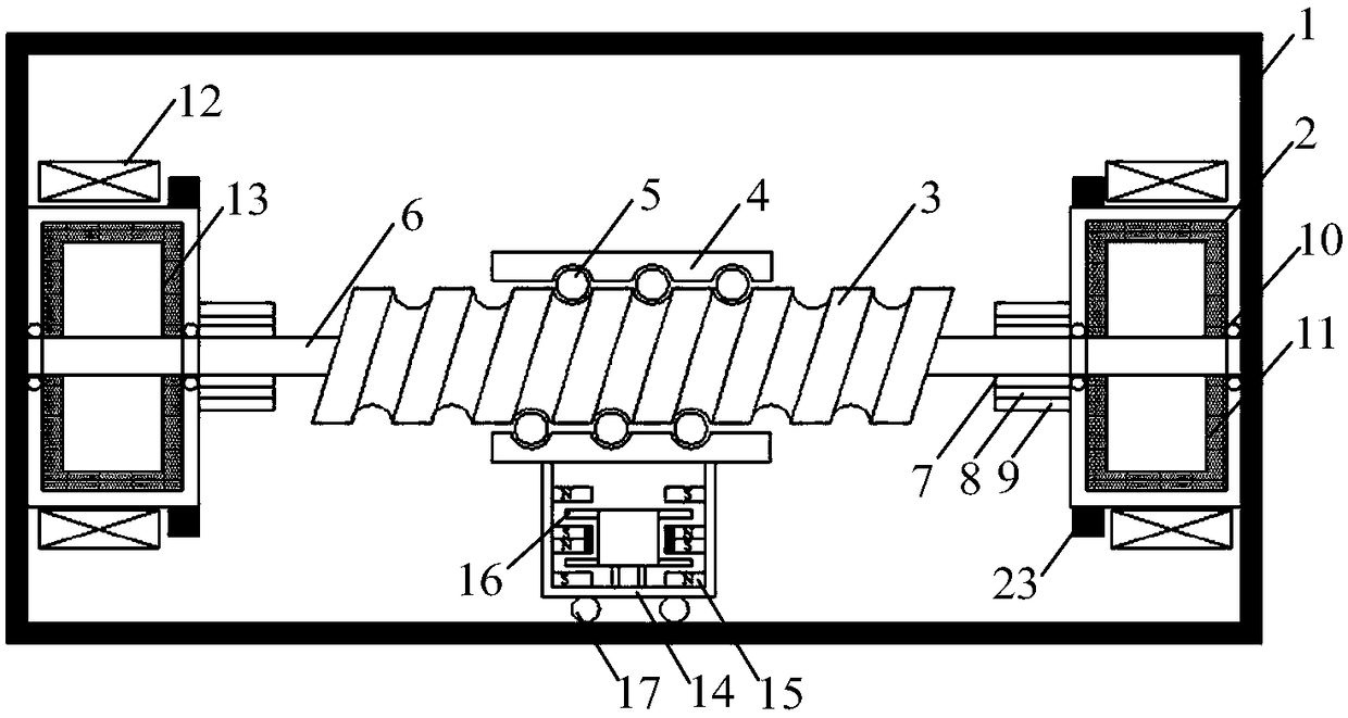
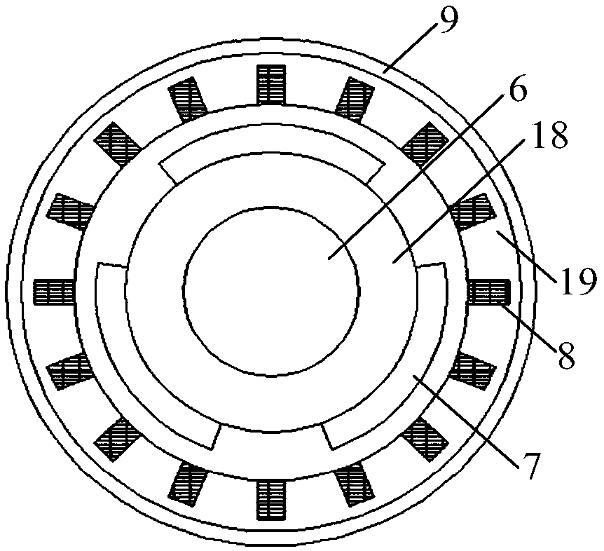
The invention discloses a self-powered type magneto-rheological damping device which comprises an outer barrel, wherein two inner barrels are fixed in the outer barrel, and the insides of the inner barrels are hollow to form damping cavities; a ball screw pair is arranged between the inner barrel, rigid rods are respectively connected to the two ends of the ball screw pair, and the two rigid rodspenetrate through the damping cavities to be connected with an inner wall of the outer barrel; a plurality of blades are fixedly arranged on the parts, in the damping cavities, of the rigid rods, theinner barrels are filled with magneto-rheological fluid, and the outsides of the inner barrels are wound by electrified coils; a movable device connected with the ball screw pair is arranged under theball screw pair, a mass block is arranged in the movable device, steel plates are arranged at the two sides of the mass block, magnets are arranged on a lateral wall of the movable device, and the steel plates are located among adjacent magnets; rotors are in interference fixed connection to the peripheries of the rigid rods, and each rotor is composed of a permanent magnet and a rotor magnet yoke; a stator core is arranged at the periphery of each rotor, a stator winding is arranged on each stator core, a stator shell is fixedly connected to the outside of each stator, and the stator shellsfixedly contact outer walls of the inner barrels.

Description

technical field [0001] The invention belongs to the field of vibration control of civil engineering, in particular to a self-powered magneto-rheological damping device, which is mainly used in controlling the vibration response of high-rise buildings and towering structures. Background technique [0002] With the progress of science and technology and the development of society, the development of building structure forms tends to be diversified and complicated, and the sensitivity of high-rise buildings to earthquake or wind load is significantly increased. Environmental vibration can easily induce large lateral vibration and deformation of the main structure, even exceeding the allowable comfort requirements. In recent years, in order to reduce the vibration response of structures, installing reasonable and effective damping systems in high-rise buildings and high-rise structures has received more and more attention. [0003] At present, according to whether there is exte...

Claims


Application Information

Patent Timeline
Patent Type & Authority Applications(China)
IPC IPC(8): F16F9/53
CPCF16F9/53F16F2224/045F16F2228/066
Inventor 田利刘俊才张睿
Owner SHANDONG UNIV
Learn More