
Electromagnetic coil sheath, coil assembly and magneto-rheological damper

A technology of electromagnetic coils and coil components, which is applied in the direction of shock absorbers, transformer/inductor coils/windings/connections, coils, etc., can solve the problems of narrow damping control range and high magnetic flux density of magnetic variable shock absorbers, and achieve improved The effect of damping adjustment range, reducing magnetic flux density, and increasing damping adjustment range

Inactive Publication Date: 2021-04-13
SHENZHEN INST OF ADVANCED TECH
View PDF8 Cites 0 Cited by
  • Summary
  • Abstract
  • Description
  • Claims
  • Application Information

AI Technical Summary

Problems solved by technology

[0004] The object of the present invention is to provide an electromagnetic coil sheath, which aims to solve the problem that the existing electromagnetic coil sheath tends to make the magnetic flux density of the magnetorheological fluid too high and the damping control range of the magnetic variable shock absorber is narrow.

Method used


Image

  • Electromagnetic coil sheath, coil assembly and magneto-rheological damper
  • Electromagnetic coil sheath, coil assembly and magneto-rheological damper
  • Electromagnetic coil sheath, coil assembly and magneto-rheological damper

Examples


Embodiment Construction

[0026] Embodiments of the present invention are described in detail below, examples of which are shown in the drawings, wherein the same or similar reference numerals designate the same or similar elements or elements having the same or similar functions throughout. The embodiments described below by referring to the figures are exemplary and are intended to explain the present invention and should not be construed as limiting the present invention.

[0027] In describing the present invention, it should be understood that the terms "length", "width", "upper", "lower", "front", "rear", "left", "right", "vertical", The orientation or positional relationship indicated by "horizontal", "top", "bottom", "inner", "outer", etc. are based on the orientation or positional relationship shown in the drawings, and are only for the convenience of describing the present invention and simplifying the description, rather than Nothing indicating or implying that a referenced device or element...


PUM


Abstract

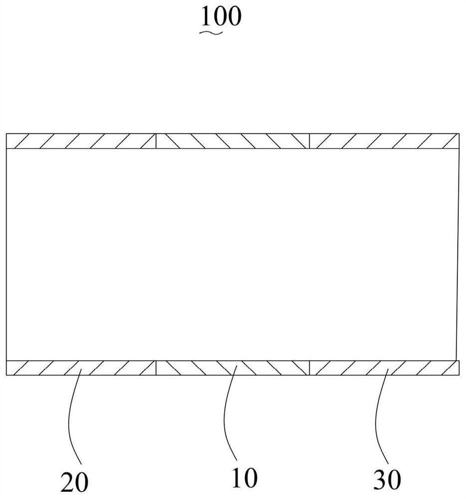
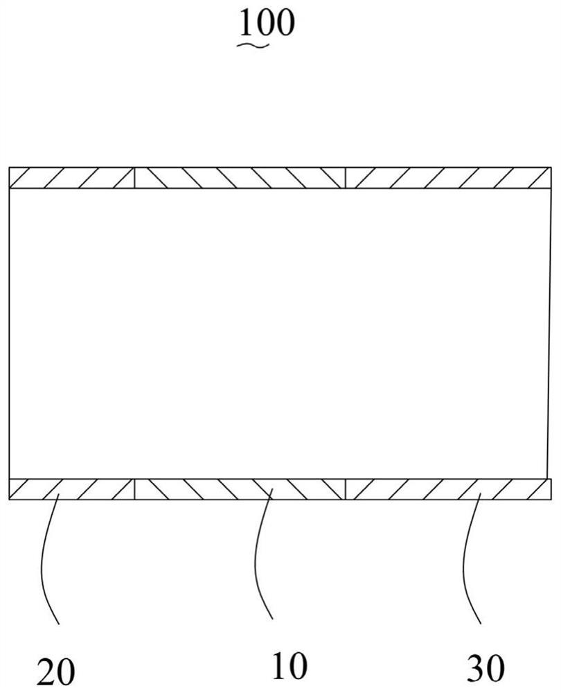
The invention relates to the technical field of automobile damping accessories, and provides an electromagnetic coil sheath, a coil assembly and a magneto-rheological damper. The electromagnetic coil sheath is used for sleeving the outer side of an electromagnetic coil of the coil assembly and is located between inner magnetizers, and the electromagnetic coil sheath comprises a diamagnetic main body of a hollow structure, a first magnetic conductive part and a second magnetic conductive part, the first magnetic conductive part and the second magnetic conductive part are respectively abutted against the corresponding inner magnetizers. The first magnetic conductive part, the diamagnetic body and the second magnetic conductive part which are connected in sequence form an annular channel with the outer magnetizer and the inner magnetizer of the coil assembly, the first magnetic conductive part and the second magnetic conductive part extend the sectional areas of the inner magnetizer and the outer magnetizer in the section direction, the unit area is increased, the magnetic flux density of magnetorheological fluid is reduced, after the magnetic flux density of the magneto-rheological fluid is reduced, the damping adjustment range of the magneto-rheological damper can be widened by continuously improving the magnetic field intensity of the electromagnetic coil.

Description

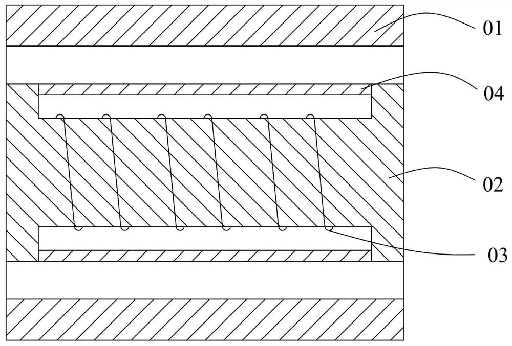
technical field [0001] 本发明涉及汽车减振配件技术领域,尤其提供一种电磁线圈护套、具有该电磁线圈护套的线圈组件以及具有该线圈组件的磁流变减振器。 Background technique [0002] 磁流变减振器的工作原理是磁流变液在活塞的推动下流经由外导磁体、内导磁体以及抗磁体组合形成的环形通道。 Specifically, please refer to figure 1 , figure 1 为线圈组件的剖面图,其中,01为外导磁体、02为内导磁体、03为电磁线圈以及04为垫圈,磁流变液在外导磁体01、内导磁02以及垫圈04组合形成的环形通道,电磁线圈03通电后产生磁场,由内导磁体02、磁流变液、外导磁体01组成磁路回路;磁流变液在磁场作用下转变成粘弹性固体,使得磁流变液的流动阻尼增大;磁流变液的阻尼大小与磁通密度正相关,只要改变磁场强度就可以改变阻尼。 [0003] 然而,根据研究显示,随着磁场强度的提高,磁流变液的磁通密度逐渐趋于磁饱和,处于磁通密度磁饱和状态后继续提高磁场强度,磁流变液流动阻尼就不再变化。以及,提高磁流变的饱和磁通密度,可以增大磁流变减振器阻尼变化范围,但磁流变液饱和磁通密度提高会伴随着磁流变液产生自身流动阻尼增大和磁流变减振器初次动作卡阻的不良后果。因此,通常磁流变液饱和磁通密度一般都比较小,这也是导致目前磁流变减振器对阻尼调控范围窄的原因。 Contents of the invention [0004] 本发明的目的提供一种电磁线圈护套,旨在解决现有的电磁线圈护套易使磁流变液的磁通密度偏高所导致的磁力变减振器的阻尼调控范围窄的问题。 [0005] In order to achieve the above object, the technical scheme adopted in the present invention is: [0006] 第一方面,本申请提供一种电磁线圈护套,用于套设在线圈组件的电磁线圈的外侧且位于内导磁体之间,包括呈中空结构的抗磁主体以及分别设于所述抗磁主体的相对两端侧的第一导磁部和第二导磁部,所述第一导磁部和所述第二导磁部分别抵接于对应的内导磁体。 [0007] 本发明的有益效果:本发明提供的电磁线圈护套,包括抗磁主...

Claims


Application Information

Patent Timeline
Patent Type & Authority Applications(China)
IPC IPC(8): H01F5/00H01F27/30H01F1/44F16F9/53F16F9/32
CPCH01F5/00H01F27/306H01F1/447F16F9/535F16F9/32
Inventor 石印洲李文飞潘仲鸣李慧云林定方
Owner SHENZHEN INST OF ADVANCED TECH
Learn More