Temperature field measurement system and method based on single camera
A measurement system and temperature field technology, which is applied in the field of temperature field measurement system based on single camera, can solve the problems of high cost and low temperature field measurement accuracy
- Summary
- Abstract
- Description
- Claims
- Application Information
AI Technical Summary
Problems solved by technology
Method used
Image
Examples
Embodiment 1
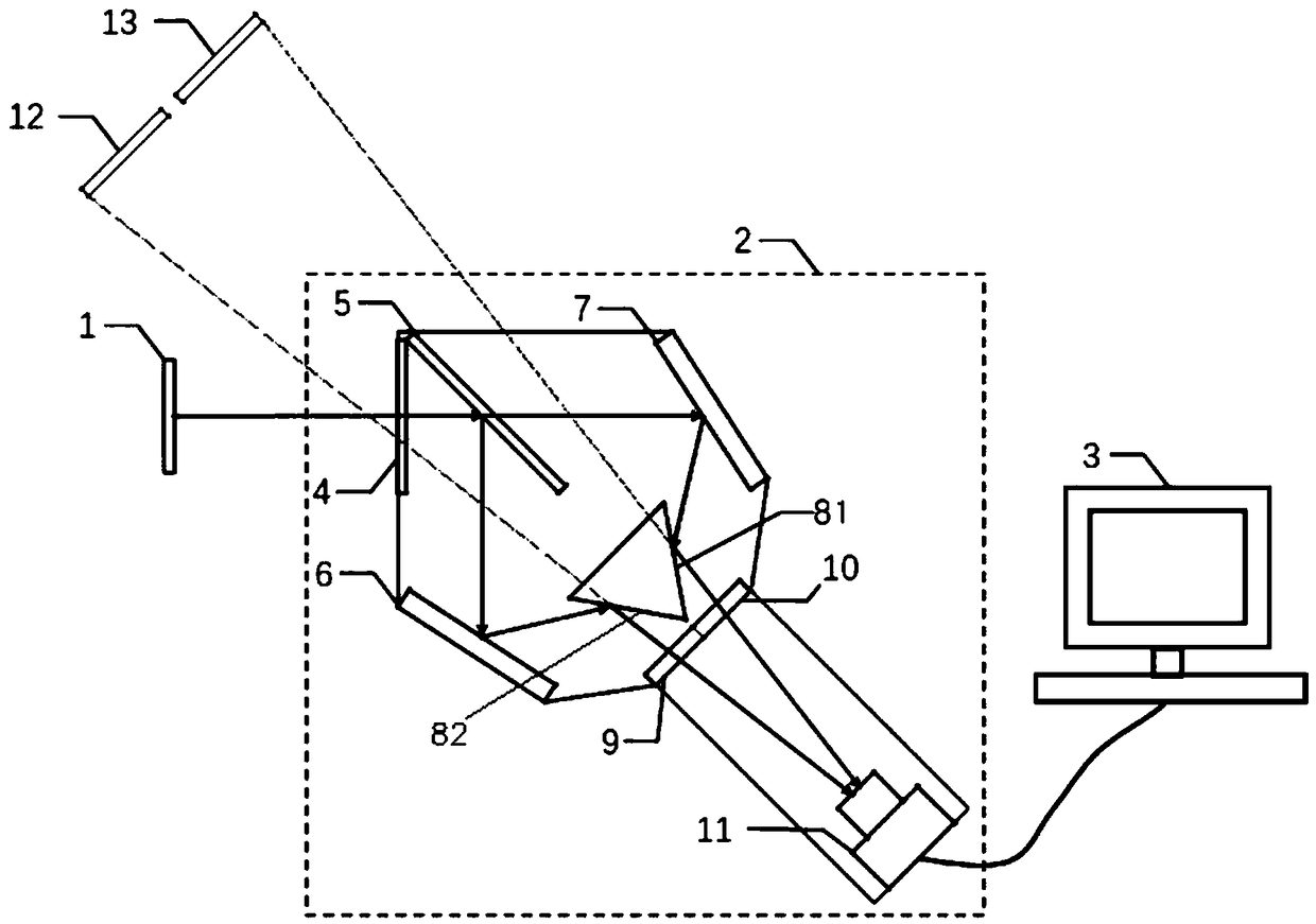
[0102] This embodiment provides a temperature field measurement system based on a single camera, which is used to measure the temperature field on the surface of the object to be tested, such as figure 1 Shown is a schematic structural diagram of a temperature field measurement system based on a single camera, including a measuring device 2 and a computing device 3;
[0103] Measuring device 2 comprises entrance window 4, plate beam splitter 5, first mirror group, second mirror group, narrow-band filter group and camera 11, and according to figure 1 Installed at the position shown; when measuring the temperature field on the surface of the DUT 1, the DUT 1 is first subjected to thermal loading, and then the DUT 1 is placed at the position facing the incident window 4, since the DUT 1 itself Infrared rays can be emitted, and after passing through the flat beam splitter 5, they are divided into exactly the same beam one and beam two, and the beam one and the beam two enter the c...
Embodiment 2
[0113] On the basis of Embodiment 1, this embodiment provides a preferred temperature field measurement system based on a single camera. For relevant parts, please refer to the description of Embodiment 1. positional relationship.
[0114] Please continue to refer figure 1, the angle between the flat beam splitter 5 and the incident window 4 is preferably 45 °, so that the light rays that are horizontally incident on the flat beam splitter 5 from the test piece 1 are converted into a horizontal beam one, and the other part is a vertical beam. Direction of beam II. The included angles between the first reflecting mirror 7 and the second reflecting mirror 6 and the flat beam splitter 5 are respectively θ, and the opening direction of the included angle θ is toward the incident window side, and 0°<θ<20°. The angle between the third reflecting mirror 81 and the fourth reflecting mirror 82 is an acute angle, which can be adjusted according to the distance between the second refle...
Embodiment 3
[0116] On the basis of Embodiment 1 and Embodiment 2, this embodiment provides a single-camera-based temperature field measurement system. For related details, reference may be made to the descriptions of Embodiment 1 and Embodiment 2. The computing device is further described in this embodiment.
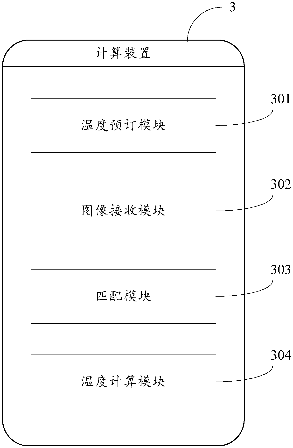
[0117] figure 2 is a schematic block diagram of a computing device, combined with figure 1 and figure 2 , the computing device 3 includes:
[0118] The temperature reservation module 301 is used to receive the target temperature value of the heated object 1, and determine the calibration coefficient K according to the target temperature value and the calibration coefficient curve, wherein the calibration coefficient curve is a correlation curve between temperature and calibration coefficient; K is the colorimetric A calibrated coefficient in the temperature measurement formula, the value of K changes with the temperature of the test piece 1. The coefficient K can be used to cor...
PUM
 Abstract
Description
Claims
Application Information
 - R&D
- Intellectual Property
- Life Sciences
- Materials
- Tech Scout
- Unparalleled Data Quality
- Higher Quality Content
- 60% Fewer Hallucinations
Browse by: Latest US Patents, China's latest patents, Technical Efficacy Thesaurus, Application Domain, Technology Topic, Popular Technical Reports.
© 2025 PatSnap. All rights reserved.Legal|Privacy policy|Modern Slavery Act Transparency Statement|Sitemap|About US| Contact US: help@patsnap.com


