Fast-plug tail cable testing connector

A technology for testing connectors and pigtail cables, applied in the direction of testing/measuring connectors, connections, conductive connections, etc., can solve the problems of abnormal antenna indicators, complex antenna structure, rework and scrap, etc., to achieve convenient operation, good replaceability, electrical The effect of accurate performance test values

Pending Publication Date: 2018-11-23
ZHENJIANG HUAZHAN ELECTRONICS SCI & TECHCO
View PDF0 Cites 4 Cited by
  • Summary
  • Abstract
  • Description
  • Claims
  • Application Information

AI Technical Summary

Problems solved by technology

[0003] At present, manufacturers can only perform double-length and double-head testing in the production process of cable assemblies before cutting and forming. Once the cable is cut into a tail cable, it cannot be connected to the test system for direct testing. After the cable is integrally welded into the antenna product, the electrical performance of the entire antenna is tested. However, due to the complex internal structure of the antenna, many parts, and dense solder joints, if the cable is defective and the antenna indicators are abnormal, it will be difficult to troubleshoot and cause a lot of rework and scrap.

Method used


Image

  • Fast-plug tail cable testing connector
  • Fast-plug tail cable testing connector
  • Fast-plug tail cable testing connector

Examples


Embodiment Construction

[0020] The present invention will be further described below in conjunction with drawings and embodiments.

[0021] In this embodiment, the end connected to the test system is the front, and the end connected to the cable is the rear.

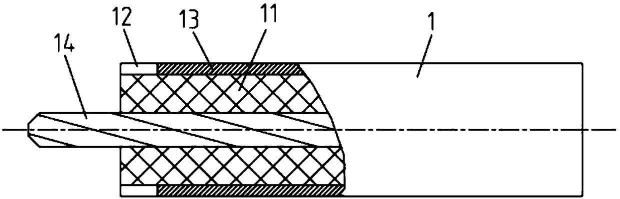
[0022] like figure 1 As shown, after the step of the cable 1 is peeled off, an air dielectric ring 12 is formed at the step of the insulating layer 11 .

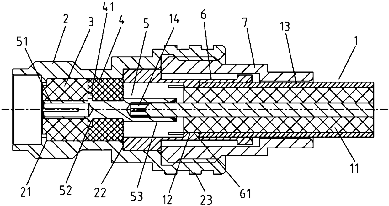
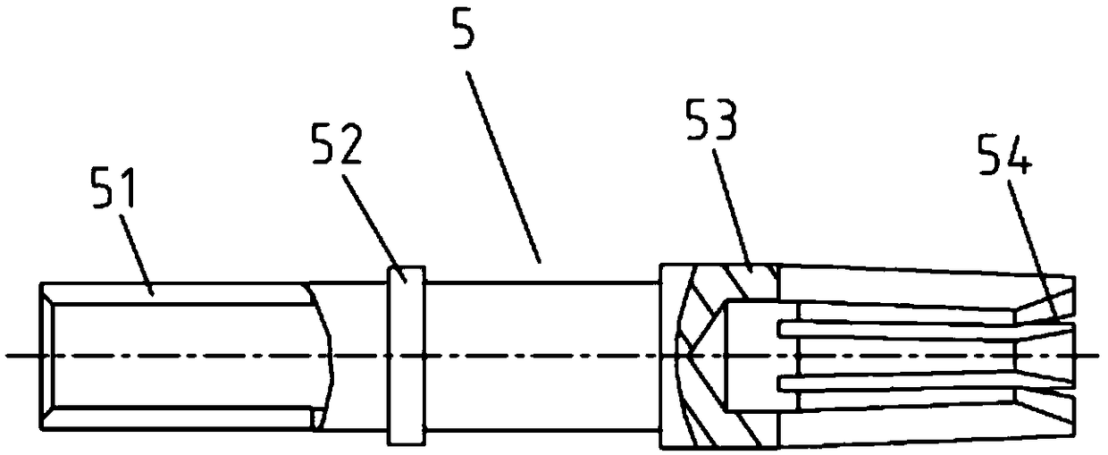
[0023] like figure 2 As shown, the present invention includes a main housing 2 , a front medium 3 , a rear medium 4 , an inner conductor 5 , a clamp 6 and a locking housing 7 . The inner hole of the main housing 2 is a stepped hole structure, and the front medium 3, the rear medium 4, the inner conductor 5 and the wire clip 6 are arranged in the inner hole of the main housing 2 in sequence from front to back, and the front side of the front medium 3 is against the main housing. On the first step 21 of the inner hole of the body 2, the rear medium 4 is fixedly set in the middle of the inne...


PUM


Abstract

The invention discloses a fast-plug tail cable testing connector, and the connector comprises a main housing, a front medium, a rear medium, an internal conductor, a wire clamp, and a locking housing.The front side of the front medium abuts against a first step of an inner hole of the main housing, and the rear medium is fixedly disposed at the central part of the internal conductor in a sleevingmanner. A front plugging connection head of the internal conductor stretches into the inner hole of the front medium, and the front side of the rear medium abuts against the rear side of the front medium. The front end face of the wire clamp abuts against a second step of the inner hole of the main housing, and compresses the rear side of the rear medium. The central part of the inner hole of thewire clamp extends out of an annular positioning platform. When a cable is inserted, an end face of the cable shielding layer abuts against the annular positioning platform, and the annular positioning platform falls into a cable air medium ring. The front end of the locking housing is in screw fit with the rear end of the inner hole of the main housing. The connector is simple in structure, andis low in cost. During testing, only the end of the tail cable needs to be inserted into the connector; after testing, the end of the tail cable is plugged out, thereby achieving the quick plugging connection and disconnection of the connector and the cable, enabling the operation to be convenient, and greatly improving the cable testing efficiency.

Description

technical field [0001] The invention relates to a radio frequency connector, in particular to a radio frequency connector for testing the electric properties of cables, and belongs to the technical field of electronic components. Background technique [0002] RF connectors and RF cable assemblies are important electronic components in modern mobile communication networks. They are widely used in various environments and occasions of mobile communications. Among them, RF cable assemblies are used in the connection between devices, structural wiring in devices and base stations. The coaxial transmission structure forming the feed network within the antenna is widely used. The main structure of the base station antenna is composed of an outer cover, a reflector, an H feed network H, and a vibrator. Among them, the signal access form of the feed network is more commonly used in the form of a tail cable. One end of the tail cable is connected to a standard port RF coaxial connect...

Claims


Application Information

Patent Timeline
Patent Type & Authority Applications(China)
IPC IPC(8): G01R1/04H01R9/05H01R13/502H01R24/40H01R24/44
CPCG01R1/0416H01R9/05H01R9/0527H01R13/502H01R24/40H01R24/44H01R2201/20
Inventor 李斌芦坤
Owner ZHENJIANG HUAZHAN ELECTRONICS SCI & TECHCO
Why Eureka
Try Eureka