Optical module

An optical module and optical receiving technology, which is applied in the field of optical communication to achieve the effect of improving the utilization rate of the casing

Active Publication Date: 2018-11-23
HISENSE BROADBAND MULTIMEDIA TECH
View PDF4 Cites 7 Cited by
  • Summary
  • Abstract
  • Description
  • Claims
  • Application Information

AI Technical Summary

Problems solved by technology

[0005] The application provides an optical module to solve the problems caused by the optical receiver and optical transmitter shell in the prior art

Method used


Image

  • Optical module
  • Optical module
  • Optical module

Examples


Embodiment Construction

[0016] In order to enable those skilled in the art to better understand the technical solutions in the embodiments of the present application, the technical solutions in the embodiments of the present application will be further described in detail below in conjunction with the accompanying drawings.

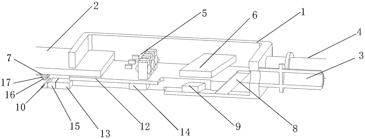
[0017] see image 3 , is a cross-sectional view of the optical module provided by the embodiment of the present application. The optical module in this embodiment includes a housing 1, one end of the PCB board 2 is fixedly connected to the housing 1, and one side of the housing 1 is provided with a light receiving adapter 3 and an optical launch adapter4. The light-receiving adapter 3 and the light-emitting device 4 are respectively provided with an adjusting sleeve, and the light-receiving adapter 3 and the light-emitting device 4 are respectively connected to one end of the corresponding adjusting sleeve through penetration welding, and the other end of the adjusting sleeve is...


PUM


Abstract

The embodiment of the invention discloses an optical module. One side of a shell is provided with an optical receiving adapter and an optical transmitting adapter and the shell is internally providedwith a laser array, a transmitting-end optical multiplexing module and a first displacement prism; one end of a PCB is arranged in the shell, and the laser array is electrically connected with the upper surface of the PCB; the lower surface of the PCB is provided with an optical receiver array; the first displacement prism propagates light from the optical receiving adapter to the lower surface ofthe PCB, and the light then passes through a receiving-end optical multiplexing module and is reflected to the optical receiver array through a reflecting surface; the laser array and the transmitting-end optical multiplexing module are arranged in the shell and corresponding to the upper surface area of the PCB; the received light is propagated to the lower surface of the PCB through the first displacement prism. A component at the receiving end and a component at the transmitting end are located at different sides of the PCB, when the optical module works, no crosstalk happens between the component at the receiving end and the component at the transmitting end, and according to the above layout mode, the utilization ratio of the shell is improved.

Description

technical field [0001] The present application relates to the technical field of optical communication, and in particular to an optical module. Background technique [0002] In the field of optical communication, an optical module is an important device for realizing photoelectric conversion. Such as figure 1 As shown, the optical module generally includes an optical receiver, an optical transmitter and a PCB board. The optical receiver and the optical transmitter are independently arranged on the PCB, and the electronic circuit is arranged on the PCB, and both the optical receiver and the optical transmitter are electrically connected with the electronic circuit on the PCB. Corresponding to the light receiver and the light emitter, a first package a and a second package b are respectively arranged, the components in the light receiver are arranged in the first package a, and the components in the light transmitter are arranged in the second tube Inside shell b. The firs...

Claims


Application Information

Patent Timeline
Patent Type & Authority Applications(China)
IPC IPC(8): G02B6/42
CPCG02B6/4214G02B6/4256G02B6/428G02B6/4287G02B6/4296
Inventor 李丹杜光超唐永正傅钦豪
Owner HISENSE BROADBAND MULTIMEDIA TECH
Why Eureka
Try Eureka