Eureka AIR delivers breakthrough ideas for toughest innovation challenges, trusted by R&D personnel around the world.

Fixed connecting structure and method for conductor and insulator supporting conductor

A technology for insulators and conductors, which is applied in the direction of connections, parts of connection devices, electrical components, etc., can solve the problems of difficulty in ensuring the fixed connection strength of insulators and conductors, affecting the bonding strength of insulators and metal cylinders, and difficult to grasp the fixed connection strength. Achieve excellent electrical product use effect, improve implementation convenience, and facilitate the effect of electric field requirements

Active Publication Date: 2018-11-23
XIAN XD SWITCHGEAR ELECTIC CO LTD +1
View PDF10 Cites 2 Cited by
  • Summary
  • Abstract
  • Description
  • Claims
  • Application Information

AI Technical Summary

Problems solved by technology

If the plastic deformation of the metal cylinder is too large, it will cause a large internal stress in the insulator, which will affect the bonding strength between the insulator and the metal cylinder
If the plastic deformation of the metal cylinder is too little, the connection strength between the metal cylinder and the conductor will be insufficient, and it will be difficult to ensure the fixed connection strength between the insulator and the conductor
[0023] In addition, during the process of wedging the metal wedge between the metal cylinder and the outer wall of the conductor, metal scraps will be generated
If these metal scraps are not cleaned thoroughly, discharge flashover may occur in the subsequent use process, which will bring hidden dangers to the quality of the product
[0024] In short, using the technical solution of the known embodiment 4, there are defects that it is difficult to grasp the strength of the fixed connection, and it is difficult to completely remove metal scraps

Method used


Image

  • Fixed connecting structure and method for conductor and insulator supporting conductor
  • Fixed connecting structure and method for conductor and insulator supporting conductor
  • Fixed connecting structure and method for conductor and insulator supporting conductor

Examples


Embodiment Construction

[0073] In order to enable those skilled in the art to better understand the technical solutions in the present invention, the technical solutions in the embodiments of the present invention will be clearly and completely described below in conjunction with the drawings in the embodiments of the present invention. Obviously, the described The embodiments are only some of the embodiments of the present invention, not all of them. Based on the embodiments of the present invention, all other embodiments obtained by persons of ordinary skill in the art without making creative efforts shall fall within the protection scope of the present invention.

[0074] It should be noted that when an element is referred to as being “disposed on” another element, it may be directly on the other element or there may also be an intervening element. When an element is referred to as being "connected to" another element, it can be directly connected to the other element or intervening elements may a...


PUM


Abstract

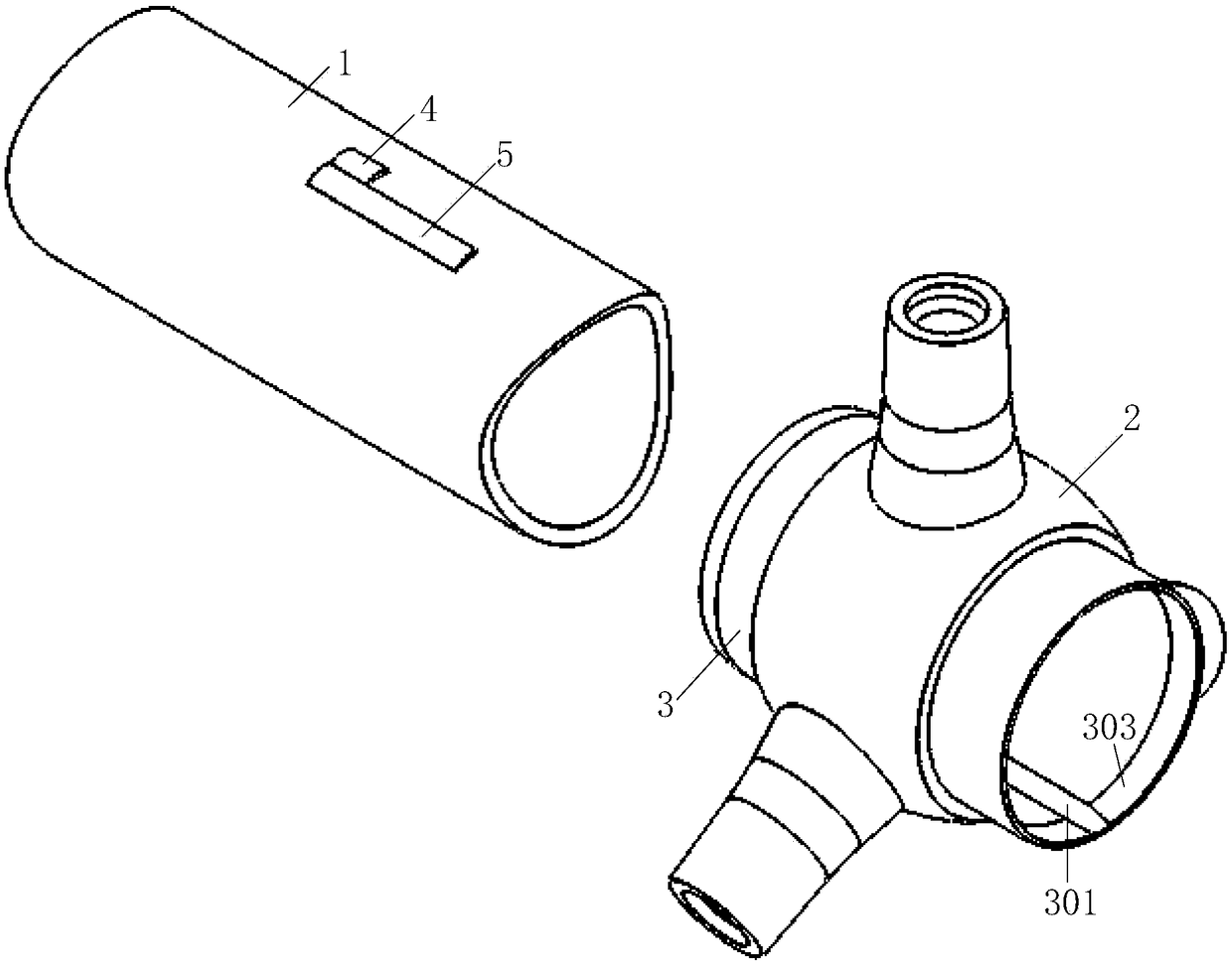
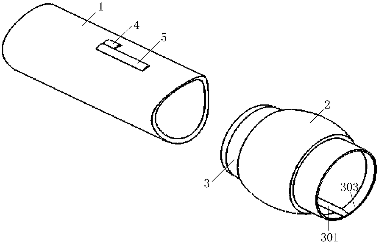
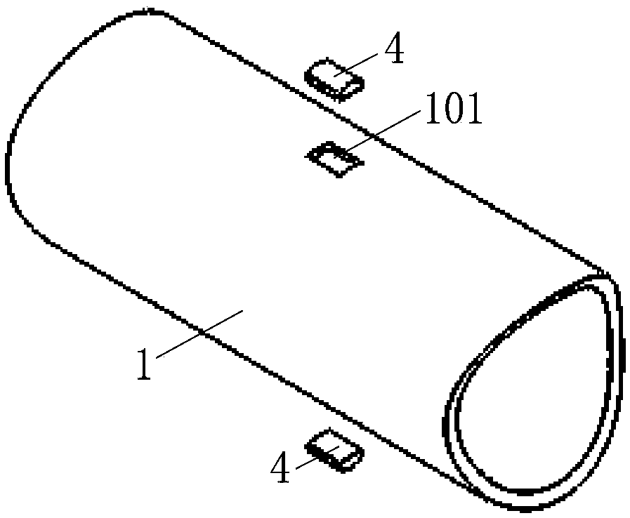
The invention provides a fixed connecting structure and a method for a conductor and an insulator supporting the conductor. First grooves are formed in the inner concave part of the outer wall of theconductor. The insulator is integrally formed outside a barrel body in a pouring manner, and the insulator sleeves the conductor. Second grooves and chutes connected to the second grooves are formed in the inner concave part of the inner wall of the barrel body. A first limiting key is embedded in the first groove and the second groove. A second limiting key is embedded in the chute, and the second limiting key is fixedly arranged between the first limiting key and the side wall of the chute. According to embodiments of the fixed connecting structure and method for the conductor and the insulator supporting the conductor, fixed connection between the conductor and the insulator supporting the conductor can be realized in an ultra-clean, normal temperature, light and low-cost manner.

Description

technical field [0001] The invention relates to the technical field of high-voltage electrical switchgear, in particular to a fixed connection structure and method for a conductor and an insulator supporting the conductor. Background technique [0002] The statements in this section only provide background information related to the present disclosure and may not constitute prior art. [0003] In the case of GIL or GIS busbar applications, a standard assembly unit for installation and disassembly usually includes a tubular shell container containing insulating medium gas. A metal tubular conductor is coaxially arranged in the shell container. The shell container and The conductors are provided with supporting insulators. No matter how the structural shape of the insulator changes, the supporting insulator and the conductor must achieve a fixed connection effect in the axial and circumferential directions. [0004] There are many existing technologies and embodiments for th...

Claims


Application Information

Patent Timeline
IPC IPC(8): H01R13/405
CPCH01R13/405
Inventor 刘锋贾昕宇吴明星谭茜茜李博强
Owner XIAN XD SWITCHGEAR ELECTIC CO LTD
Why Eureka
Eureka Blog
Learn More