Statistical type UPFC power flow optimization method

An optimization method and statistical technology, applied to AC network circuits, AC networks with the same frequency from different sources, circuit devices, etc., can solve the problems of low utilization rate of UPFC, idle resources, waste, etc.

Inactive Publication Date: 2018-11-23
NORTH CHINA ELECTRIC POWER UNIV (BAODING)
View PDF0 Cites 0 Cited by
  • Summary
  • Abstract
  • Description
  • Claims
  • Application Information

AI Technical Summary

Problems solved by technology

However, when the system is running normally, UPFC does not work, which will result in a low ...

Method used


Image

  • Statistical type UPFC power flow optimization method
  • Statistical type UPFC power flow optimization method
  • Statistical type UPFC power flow optimization method

Examples


Embodiment Construction

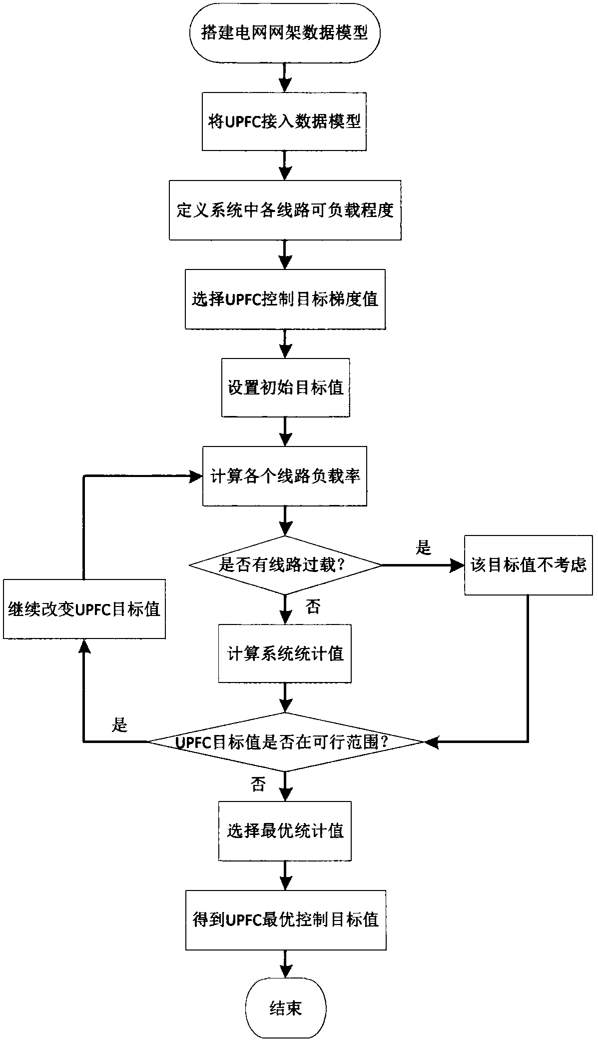
[0035] A statistical UPFC power flow optimization method, comprising the following steps:

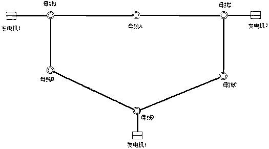
[0036] (1). Build the data model of the grid grid;

[0037] (2). Connect UPFC to the data model;

[0038] (3). Define the loadability of each line according to the line characteristics in the system;

[0039] (4). Select the UPFC control target gradient value according to the UPFC adjustment range and the thermal stability limit of the line;

[0040] (5). Calculate the load rate of each line in the system under each gradient, and go to step (6) or (7) according to the situation;

[0041] (6). If there is no circuit overload in the system under the gradient, then calculate the statistical value;

[0042] (7). If the line power in the system under this gradient exceeds its own thermal stability limit, it will not be considered;

[0043] (8). According to the calculation results of steps (5) to (7), select the optimal target value of UPFC.

[0044] In step (1), power system simulation...


PUM


Abstract

The invention aims to provide a statistical type UPFC power flow optimization method. The network power flow state is represented by the statistical data. By means of the method, a control target value of UPFC can be provided for steady-state operation. According to the method, the power flow control effect of UPFC can be quantified, and a control target value suitable for a specific power grid isselected. Meanwhile, all lines in the network are considered, and the load degree of the power flow of each line can be defined according to the characteristics of the power grid. Reference can alsobe provided for power grid planning, running and other aspects of UPFC engineering access.

Description

technical field [0001] The invention belongs to the field of power systems, and in particular relates to a statistical UPFC power flow optimization method. Background technique [0002] The Westinghouse Technology Center in the United States first proposed the concept of Unified Power Flow Controller (UPFC) in 1991. UPFC combines the flexible control methods of many FACTS devices and can handle almost all power flow control problems and transmission line compensation problems. Considered the most creative and powerful FACTS element. Among them, power flow control is the core function of UPFC. [0003] At present, academic research on UPFC mostly focuses on system modeling and control strategies. In engineering applications, UPFC is usually installed on important transmission sections, aiming to meet the N-1 check of the transmission section, that is, after a circuit failure in the section, the power of other lines will not exceed its own thermal stability limit, thereby in...

Claims


Application Information

Patent Timeline
IPC IPC(8): H02J3/06
CPCH02J3/06H02J2203/20
Inventor 高雯曼任建文
Owner NORTH CHINA ELECTRIC POWER UNIV (BAODING)
Why Eureka
Try Eureka