
Prefabricated inspection well die and technology thereof for manufacturing inspection well

A technology for inspection wells and molds, applied in molds, manufacturing tools, strengthening molding, etc., can solve problems such as uneven product quality, low production efficiency, unreasonable inspection well molds or unreasonable processes, and achieve good product quality and production efficiency. High, fast combined effects

Active Publication Date: 2018-11-27
HUBEI XINGBAO TECH CO LTD
View PDF7 Cites 10 Cited by
  • Summary
  • Abstract
  • Description
  • Claims
  • Application Information

AI Technical Summary

Problems solved by technology

[0003] In the production of existing prefabricated inspection wells, due to unreasonable inspection well molds or processes, the production efficiency is low and the product quality is uneven

Method used


Image

  • Prefabricated inspection well die and technology thereof for manufacturing inspection well
  • Prefabricated inspection well die and technology thereof for manufacturing inspection well
  • Prefabricated inspection well die and technology thereof for manufacturing inspection well

Examples


Embodiment 1

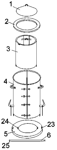
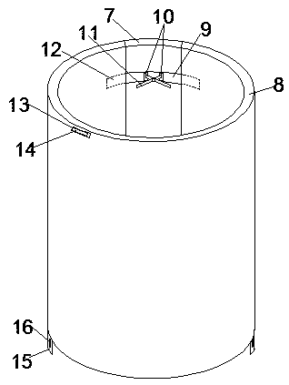
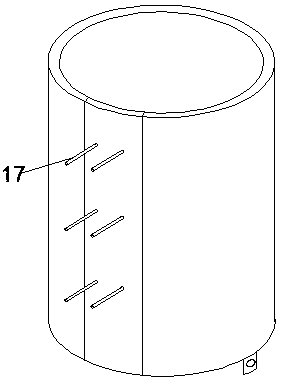
[0033] Example 1 A prefabricated inspection well mold, see figure 1 , including an outer mold 4, an inner mold 3, a bottom tray 5, an inner mold cover 1 and a well ring mold 2. During installation, the outer mold is set outside the inner mold, and an annular cavity is formed between the outer mold and the inner mold. The inner mold cover is conical, and its bottom surface is in contact with the top of the inner mold, and the bottom tray is installed under the inner mold and the outer mold. The outer mold includes two vertically symmetrical semi-cylindrical outer mold units, the corresponding vertical sides of the two outer mold units are hinged by hinges, and the corresponding vertical sides of the other side are provided with a plurality of latches along the edge Type clamp 20, unclamping or locking the bolt type clamp can quickly disassemble or combine the outer mold. There are two symmetrically arranged outer mold feet 22 extending downward from the bottom of the outer mol...

Embodiment 2

[0038] Embodiment 2 A process for making an inspection well, comprising the following steps:

[0039] S1. Clean the prefabricated inspection well mold and apply a release agent on the outer surface of the inner mold and the inner surface of the outer mold;

[0040] S2. After assembling the mold, put the reinforcement skeleton into the annular cavity and fit the skeleton with the groove of the steel rod on the inner mold;

[0041] S3. Send concrete into the annular cavity through the distributor until the feeding height is 2-4cm higher than the height of the inner mold;

[0042] S4. Hoist and transfer the mold containing concrete to the plate vibrator, after vibrating for 5 minutes, cover the well ring mold, compact it, and let it stand for 5-10 minutes;

[0043] S5. Remove the well ring mold and the inner mold cover, open the latch type clamp and the hasp, pull out the short rod, and after taking off the outer mold, hold the support rod tightly to separate the arc-shaped plat...


PUM


Abstract

The invention discloses a prefabricated inspection well die and a technology thereof for manufacturing an inspection well, and belongs to the technical field of production of inspection wells. The prefabricated inspection well die comprises an outer die body, an inner die body, a bottom tray, an inner die cover and a walling crib die body; the inner die body comprises a large arc pillar and a small arc pillar which are capable of being spliced into a cylinder, two lines of steel bars are vertically arranged on the outer wall of the small arc pillar, and clamping devices are arranged at the upper end and the lower end of the inner wall of the small arc pillar; four foot holes are formed in the bottom tray and correspond to outer die feet and inner die feet, the inner die cover is conical, and the walling crib die body is annular. The technology for manufacturing the inspection well comprises six steps. The prefabricated inspection well die and the technology thereof have the advantagesthat the production efficiency is high, the quality of finished products is high, the finished product rate is increased by 1.5 times under the same condition, the feeding amount of concrete is lowered, the energy is saved, and the economic benefit is obvious.

Description

technical field [0001] The invention belongs to the technical field of inspection well production, and in particular relates to a prefabricated inspection well mold and a process for manufacturing the inspection well. Background technique [0002] The inspection well is set up for the maintenance of urban underground infrastructure such as power supply, water supply, drainage, sewage discharge, communication, cable TV, gas pipes, and street lamp lines, and is convenient for installation. At present, most of the inspection wells used in our country are brick-built structures, with long construction period and complicated process, and poor durability, which makes the manufacture and installation of prefabricated inspection wells more necessary. Through the prefabricated reinforced concrete inspection well, the service life of the inspection well is effectively extended, the frequency of repeated road construction is reduced, and unnecessary road digging is saved, which ensures...

Claims


Application Information

Patent Timeline
IPC IPC(8): B28B21/82B28B21/14B28B21/56
CPCB28B21/14B28B21/56B28B21/82
Inventor 刘伟元廖春波王东民
Owner HUBEI XINGBAO TECH CO LTD
Learn More