Method for building ground stable base of wire rod

A base and ground technology, which is applied in the field of construction of utility poles in urban power grids, can solve problems such as damage extension, influence on towers, and loss of support wires on wire towers, and achieve strong stability and the effect of not easily collapsing

Active Publication Date: 2018-11-27
ZHENJIANG COLLEGE
5 Cites 0 Cited by

AI-Extracted Technical Summary

Problems solved by technology

[0002] One of the reasons for the destruction of the wire towers currently installed in mountainous areas is ground subsidence, which can cause the wire towers to lose their ability to support the wires, and even the collapsed or tilted towers will drag the wires. Topple other pylons, causing massive damage to the electrical wiring system
Generally, the site is fundamentally f...

Method used

Between the two adjacent walls on the left and right, there is a phase-changing column, and the phase-changing column is divided into the first half cylinder 6 and the second half cylinder 7, and the plane of the first half cylinder 6 is provided with a limit Slide rail 8, on the plane of the second half cylinder 7, limit chute 9 is arranged, and limit slide rail 8 buckles in the limit chute 9 and moves, and described first half cylinder 6 and second half cylinder 7 There are several sockets 10 distributed on the curved surface of the arc surface, the first half cylinder 6 is connected to one wall, the second half cylinder 7 is connected to the other side wall, and the latch 5 of the unit board 2 is inserted into the first half cylinder 6 or in the socket 10 of the second semi-column 7, the pole is located in the center of the area surrounded by several walls, the area is filled with concrete, and the multiple walls are used to enclose the base of the city together, and the fixed connection between the walls , more stable, and one of the walls will not collapse.
Described unit plate 2 is provided with clasp on one side towards utility pole, walks around utility pole and is provided with steel wire 11, and the two ends o...

Abstract

The invention discloses a method for building a ground stable base of a wire rod. Antiskid bases are placed continuously along a drawn line, then a plurality of unit plates are installed on the antiskid bases to form wall bodies, a phase change column is arranged between the two wall bodies, according to the height positions of the wall bodies, a first half cylinder and a second half cylinder arestaggered, then waterproofing treatment is carried out, the wire rod is placed for fixing, and lastly, concrete is injected. Compared with the prior art, the method for building the ground stable baseof the wire rod has the advantages that the wire rod can be built on arbitrary terrain, each unit plate and an adjacent unit plate are pulled and fixed, so that the enclosed wall bodies have quite strong stability, and a safe construction environment and a long and safe use environment are created for wire rod building.

Application Domain

TowersBuilding material handling

Technology Topic

TerrainStructural engineering +1

Image

  • Method for building ground stable base of wire rod
  • Method for building ground stable base of wire rod
  • Method for building ground stable base of wire rod

Examples

  • Experimental program(1)

Example Embodiment

[0023] The preferred technical solution of the present invention will be described in detail below with reference to the accompanying drawings.
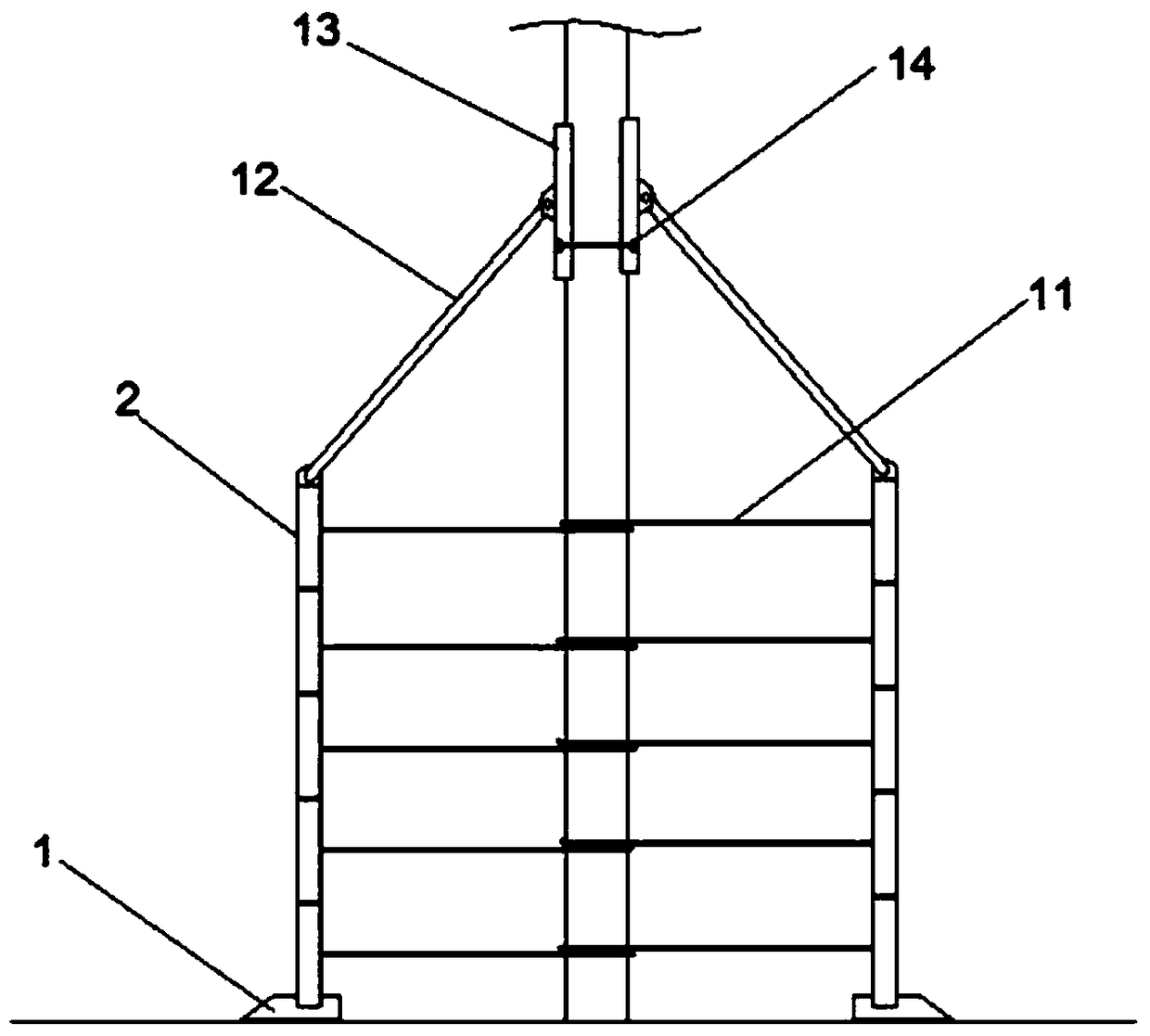
[0024] The method for constructing a wire pole ground stable base of the present invention is based on a stable base structure and includes a plurality of non-slip bases 1 arranged on the ground, the plurality of non-slip bases 1 are surrounded in a circular shape, and are poured between two adjacent non-slip bases 1 There is cement, the non-slip base 1 is provided with a trough, and the bottom unit plate 2 is arranged in the trough.
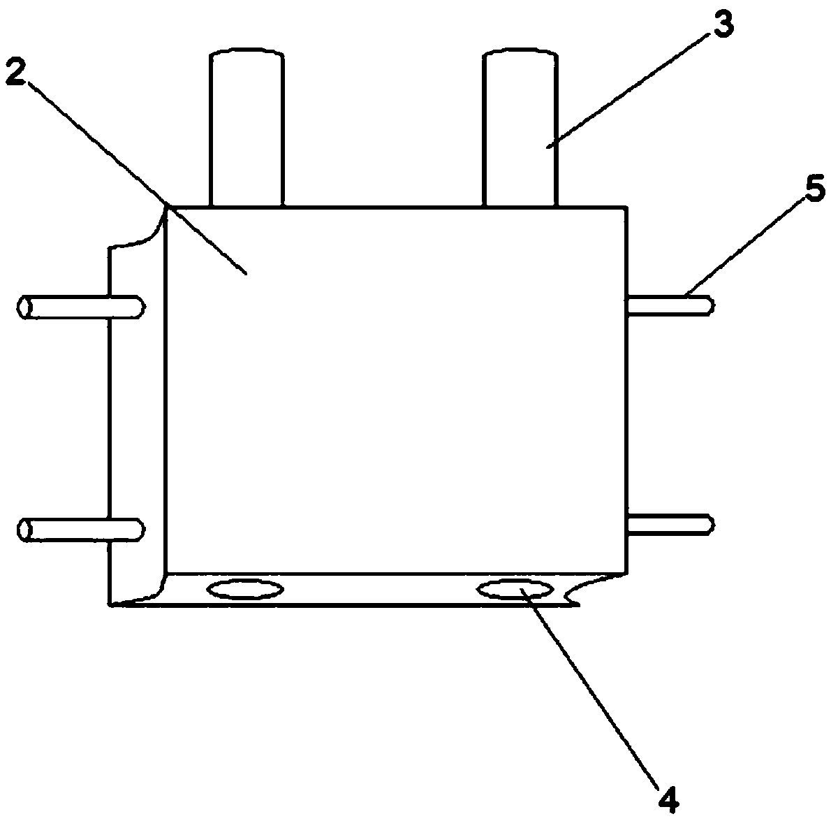
[0025] The upper edge of the unit board 2 has a pin 3, the lower edge has a pin hole 4, the pin 3 of the lower unit board 2 is inserted into the pin hole 4 of the upper unit board 2, and the side of the unit board 2 is a longitudinal semicircular concave Groove, the semicircular groove is provided with an outward-facing pin 5, and a plurality of unit boards 2 are stacked up and down to form a wall;
[0026] A phase-shifting column is arranged between the two adjacent walls on the left and right. The phase-shifting column is divided into a first half-pillar 6 and a second half-pillar 7, and a limited slide rail 8 is arranged on the plane of the first half-pillar 6 , The second half-cylinder 7 is provided with a limit chute 9 on the plane, the limit slide 8 is buckled into the limit chute 9 to move, the arc surfaces of the first half-cylinder 6 and the second half-cylinder 7 Several sockets 10 are distributed on the surface. The first half-cylinder 6 is connected to one side wall, the second half-cylinder 7 is connected to the other side wall, and the pin 5 of the unit board 2 is inserted into the first half-cylinder 6 or In the socket 10 of the two-half column 7, the wire rod is located in the center of the area surrounded by several walls, the area is filled with concrete, and the multiple walls share the base of the city, and the fixed connection between the walls is more reliable Stable, and one of the walls will not collapse.
[0027] The reinforcement is nailed into the ground inside the base wall, and after the concrete is injected, the tensile force between the concrete block and the ground can be further improved.
[0028] The unit plate 2 is provided with a buckle ring on the side facing the wire rod, and a steel wire 11 is provided around the wire rod. The two ends of the wire 11 are fixed on the buckle ring. The wire rod is tied to each unit plate 2 to ensure The unity of the unit board 2 and the wire rod.
[0029] The edge of the upper unit board 2 and the lower unit board 2 is filled with quick-drying glue, and the contact position of the unit board 2 with the disguised column is also filled with quick-drying glue. On the one hand, it is to place the concrete that intrudes from the crack into the interior. It also improves the rigidity of the connection between the wall and the wall.
[0030] The uppermost unit plate 2 is provided with a support rod 12, one end of the support rod 12 is hinged to the upper edge of the unit plate 2, and the other end of the support rod 12 is provided with an arc plate 13, and the concave surface of the arc plate 13 is attached to the wire rod To avoid breakage of the higher wire rod.
[0031] The convex surface of the arc-shaped plate 13 is provided with a horizontally arranged wire groove 14 so that the arc-shaped plate 13 can be effectively attached to the wire rod, which increases the friction force and plays a role of stable support.
[0032] The plurality of sockets 10 on the surface of the first half-cylinder 6 or the second half-cylinder 7 are equidistantly distributed in a circle of the sockets 10 along the radial direction of the phase-changing column. Several circles of sockets 10 are provided on the phase-changing column. The more jacks 10 in the circle, the more the angle formed between the walls changes, which can form a larger area of ​​the base, which can form a base of irregular land occupation structure, adapt to the harsh construction environment, and is suitable for hillsides, etc. Where the open space is limited, and the more the number of circles, the greater the fault tolerance rate of the two adjacent walls staggered up and down, which can meet more uneven ground construction.
[0033] The specific embodiments described above further describe the purpose, technical solutions and beneficial effects of the present invention in detail. It should be understood that the above are only specific embodiments of the present invention and are not intended to limit the present invention. Any modification, equivalent replacement, improvement, etc., made within the spirit and principle of the present invention shall be included in the protection scope of the present invention.

PUM

no PUM

Description & Claims & Application Information

We can also present the details of the Description, Claims and Application information to help users get a comprehensive understanding of the technical details of the patent, such as background art, summary of invention, brief description of drawings, description of embodiments, and other original content. On the other hand, users can also determine the specific scope of protection of the technology through the list of claims; as well as understand the changes in the life cycle of the technology with the presentation of the patent timeline. Login to view more.

Similar technology patents

Membrane method separation purification technology of emulsified oil-containing wastewater

InactiveCN105712514AThe equipment process is simpleStrong stability
Owner:KUNSHAN DONGDA ZHIHUI TECH CONSULTANT

Medical cold compress patch raw material and preparation technology

ActiveCN109091289AStrong stabilitygood stability and adhesion
Owner:CHONGQING HUALUN MEDICAL INSTR

Building energy consumption prediction method and system based on improved LSTM

PendingCN114742278AImprove convergence rateStrong stability
Owner:XI'AN UNIVERSITY OF ARCHITECTURE AND TECHNOLOGY

Classification and recommendation of technical efficacy words

  • Strong stability
  • Not easy to collapse

Working area ranking method and ranking system for robot

Owner:平邑经济开发区投资发展有限公司

Method for preparing high-concentration nano silver monomer dispersion liquid

InactiveCN105268991AStrong stabilityWide pH controllable range
Owner:SHANGHAI NAT ENG RES CENT FORNANOTECH

Hybrid type tilting rotor-wing unmanned aerial vehicle

PendingCN106882371ASimple vertical operationStrong stability
Owner:北京天宇新超航空科技有限公司

Resource load balancing control method and cluster scheduler

ActiveCN108009016AStrong stabilityStrong predictability
Owner:HUAWEI TECH CO LTD

Wearable papermaking coating scraper

InactiveCN1834343AHigh bonding strengthNot easy to collapse
Owner:SHANDONG UNIV OF SCI & TECH

Preparation method of hydrogenation catalyst

ActiveCN103769157ANot easy to collapseuniform grain size
Owner:CHINA PETROLEUM & CHEM CORP +1

Mushroom and ham filling and preparation method thereof

InactiveCN101611859Agood shapeNot easy to collapse
Owner:上海绿缘食品有限公司

Wood slit filling putty

InactiveCN107163659ANot easy to collapseGood smoothing effect
Owner:贵港市鑫宏木业有限公司

Solid-state alcohol preservative and manufacturing method thereof

InactiveCN104305472AMolding state is stableNot easy to collapse
Owner:GUANGDONG GUANGYI TECH IND
Why Eureka
Try Eureka