Adjustable concrete pouring chute device

A concrete and adjustable technology, applied in the construction, building structure, construction material processing and other directions, can solve the problems of uneconomical, heavy steel support, large amount of engineering, etc., to improve the integrity, convenient adjustment and simple operation. Effect

Inactive Publication Date: 2018-11-27
WUHAN YIYE CONSTR ENG
View PDF11 Cites 2 Cited by
  • Summary
  • Abstract
  • Description
  • Claims
  • Application Information

AI Technical Summary

Problems solved by technology

[0003] There are currently two methods for concrete pouring chutes: one is to customize the chute on site according to the actual needs of the construction, such as pouring height difference, pouring distance and other specific parameters. Formwork and wooden squares are used to customize the chute on the bracket. In this way, scaffolding must be erected as the chute support first, which requires a large amount of engineering and is not economical. Moreover, steel pipe scaffolding is used as the support, which is easily affected by complex factors on the construction site and has potential safety hazards.
The other is to use steel bars to weld the fixed bracket according to the construction requirements, and weld U-shaped steel plates on the bracket as the chute. In this way, the chute will move with the pouring progress, and the steel bracket is too bulky and not conducive to movement.
[0004] The above two concrete pouring chutes cannot meet the requirements of convenient use, fast movement, good adjustability and high stability at the same time.

Method used


Image

  • Adjustable concrete pouring chute device
  • Adjustable concrete pouring chute device

Examples


Embodiment Construction

[0017] The present invention will be further described below in conjunction with the accompanying drawings and embodiments.

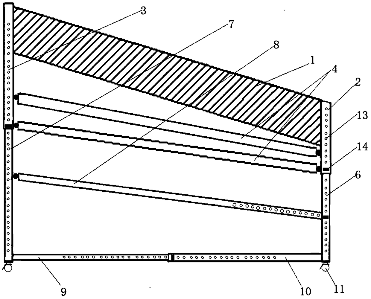
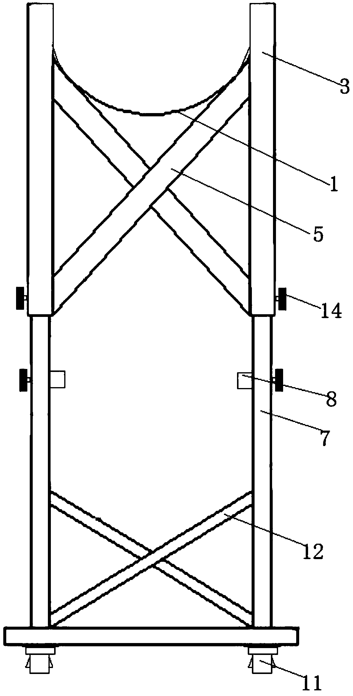
[0018] like figure 1 and figure 2 As shown, an adjustable concrete pouring chute device includes an upper frame, a lower frame and a U-shaped plate 1; the upper frame includes two vertical upper front bars 2, an upper front fixing bar that fixes the two upper front bars 2, two A vertical upper rear bar 3, an upper rear fixing bar 5 fixed by two upper rear bars 3, an upper reinforcing bar 4 hinged with the upper front bar 2 and the upper rear bar 3 on the same side at both ends, and the same side At least two parallel upper reinforcing bars 4 are arranged between the upper front bar 2 and the upper rear bar 3; the lower frame includes two vertical lower front bars 6, a lower front fixing bar for fixing the two lower front bars 6, Two vertical lower rear rods 7, the lower rear fixed rod 12 fixed by two lower rear rods 7, the horizontal rod one 10 fixed...


PUM


Abstract

The invention relates to an adjustable concrete pouring chute device. The chute device comprises an upper frame, a lower frame and a U-shaped plate. The upper frame comprises upper front rods, upper front fixed rods, upper rear rods, upper rear fixed rods and upper reinforcing rods. The lower frame comprises lower front rods, lower front fixed rods, lower rear rods, lower rear fixed rods, a firsthorizontal rod, a second horizontal rod, lower reinforcing rods and casters. The upper front rods and the corresponding lower front rods are in sleeve connection and fixed through bolts by adjustment.The upper rear rods and the corresponding lower rear rods are in sleeve connection and fixed through bolts by adjustment. The first horizontal rod and the second horizontal rod on the same side are in sleeve connection and fixed through bolts by adjustment. The lower reinforcing rods are fixed with the lower rear rods or the lower front rods on the same side through bolts by adjustment. The U-shaped plate is fixed in the space formed by the tops of the two upper front rods and the two upper rear rods. The device can adjust the position, the height and the slope of a chute and is stable in structure, simple in operation and simple in installation.

Description

technical field [0001] The invention belongs to the field of building construction, and in particular relates to an adjustable concrete pouring chute device. Background technique [0002] In the process of large-volume concrete pouring, large-area concrete pouring, concrete pouring with drop structures, and concrete pouring with limited construction conditions, chutes are often used. The speed of concrete pouring in chutes is fast, the cost is low, and the scope is large, making up for pumping. Insufficient concrete pouring. [0003] There are currently two methods for concrete pouring chutes: one is to customize the chute on site according to the actual needs of the construction, such as pouring height difference, pouring distance and other specific parameters. Templates and wooden squares are used to customize the chute on the bracket. In this way, scaffolding must be erected as the chute support first, which requires a large amount of engineering and is uneconomical. Mor...

Claims


Application Information

Patent Timeline
Patent Type & Authority Applications(China)
IPC IPC(8): E04G21/04
CPCE04G21/0481
Inventor 方志成廖红玉甘艳生高扬
Owner WUHAN YIYE CONSTR ENG
Why Eureka
Try Eureka