Cross joint grouting pipeline of concrete arch dam or gravity-type arch dam and manufacturing method of cross joint grouting pipeline

A production method and concrete technology, which are applied to arch dams, dams, ceramic forming cores, etc., can solve the problems of the slurry outlet of the grouting pipe being not easily blocked and the slurry outlet of the grouting pipe being easily blocked, so as to reduce the number of grouting pipelines. The effect of layout, material saving and smooth pulping

Pending Publication Date: 2019-08-16
SINOHYDRO BUREAU 16 CO LTD
View PDF0 Cites 0 Cited by
  • Summary
  • Abstract
  • Description
  • Claims
  • Application Information

AI Technical Summary

Problems solved by technology

[0004] The purpose of the present invention is to overcome the defect that the grout outlet of the riser pipe is easily blocked and directly affects the grouting quality of the transverse joint in the existing concrete dam transverse joint grouting, and to provide a concrete arch dam or concrete arch dam in which the grout outlet of the riser pipe is not easily blocked. Transverse joint grouting pipeline of gravity arch dam and manufacturing method thereof, in order to improve the quality of transverse joint grouting

Method used


Image

  • Cross joint grouting pipeline of concrete arch dam or gravity-type arch dam and manufacturing method of cross joint grouting pipeline
  • Cross joint grouting pipeline of concrete arch dam or gravity-type arch dam and manufacturing method of cross joint grouting pipeline
  • Cross joint grouting pipeline of concrete arch dam or gravity-type arch dam and manufacturing method of cross joint grouting pipeline

Examples


Embodiment Construction

[0033] The present invention will be described in detail below in conjunction with the drawings. The enumerated embodiments can enable those skilled in the art to better understand the present invention, but do not limit the present invention in any form.

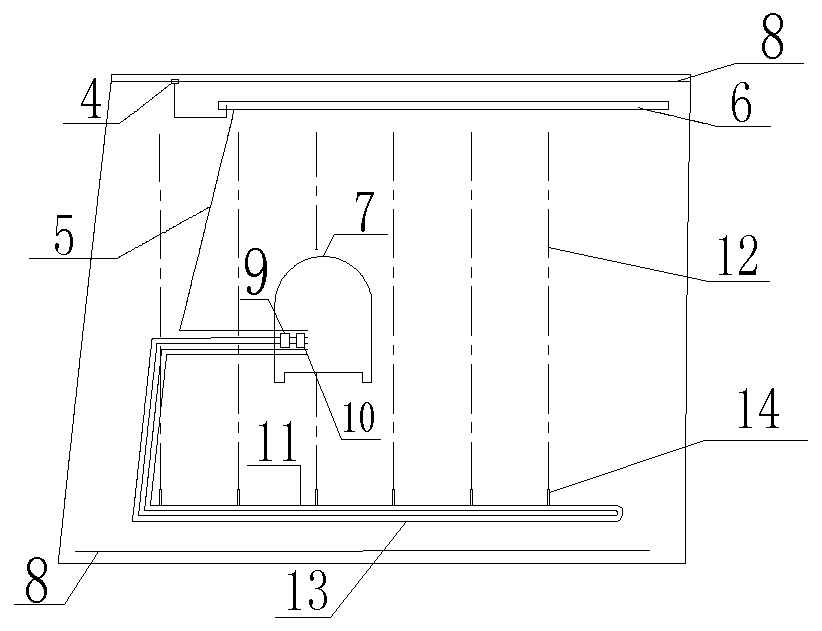
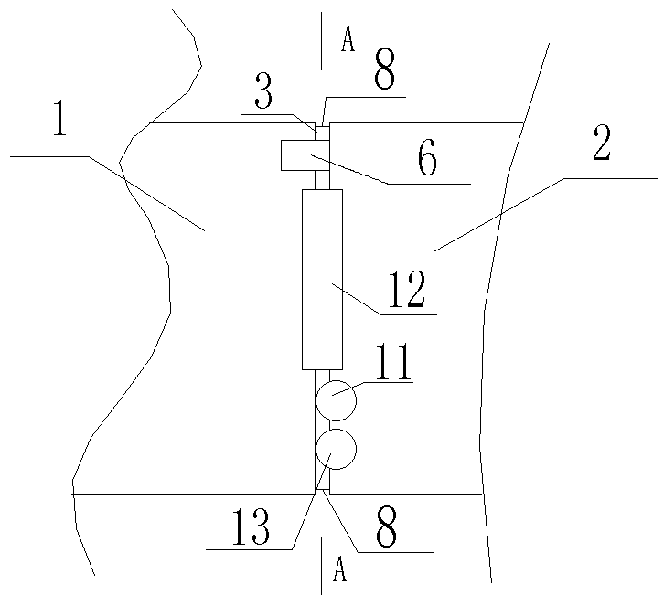
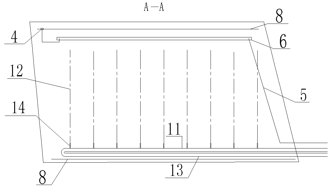
[0034] Such as Figure 1-5 As shown, a transverse joint grouting pipeline of a concrete arch dam or a gravity arch dam is improved on the basis of the existing concrete dam transverse joint grouting technology, retaining the grout inlet pipe 11, the grout return pipe 13 and the grouting pipes required for grouting. Exhaust pipe 5, exhaust groove 6, exhaust pulp box 4 and spare pipeline etc. The standby pipeline is the same group of grout inlet and return pipes as the main grouting pipeline. Since the inlet and return grout pipes are buried in the concrete, one more set should be buried to ensure the smooth progress of the construction. The slurry inlet pipe, the slurry return pipe and the spare pipeline are arranged on the...


PUM


Abstract

The invention discloses a cross joint grouting pipeline of a concrete arch dam or a gravity-type arch dam. According to the key points of the cross joint grouting pipeline, the cross joint grouting pipeline is constituted by a grout inlet pipe, grout rising pipes and a grout return pipe, each grout rising pipe is made of concrete and directly manufactured in a cross joint, and the pipe diameter ofthe grout rising pipes is greater than the width of the cross joint. A grout rising pipe constituted by a closed real object pipe is omitted, pipe cavities of the grout rising pipes are formed in thetwo sides of the cross joint while concrete is poured, the grout rising pipes are automatically formed, an inflating pipe is creatively utilized as a second pipeline mold core, the grout rising pipesare penetrated by the cross joint and communicate with the cross joint, a whole grout rising pipe joint serves as a grout discharging outlet, the blocking problem is solved, grout discharging is rapid and uniform, and the working efficiency and the grouting quality are improved. The cross joint grouting pipeline is simple in structure, easy to operate, convenient to construct and high in efficacy; and the hole forming quality is ensured, and systematical forming of a joint grouting pipeline is met. The cross joint grouting pipeline can be recycled repeatedly and is economical and durable, theconstruction cost is lowered, the strength of labor force is reduced, and smooth pouring is ensured effectively.

Description

technical field [0001] The invention relates to a transverse joint grouting pipeline of a concrete arch dam or a gravity arch dam and a manufacturing method thereof. Background technique [0002] As described in ZL2016110529627 Method for Grouting Transverse Joints of Concrete Dams, concrete dams are generally provided with transverse joints every 20m or so along the direction of the dam axis. The quality of the transverse joint grouting directly affects the integrity of the concrete dam. The grout inlet pipe, the grout return pipe, the grout outlet, the grout groove, the grout groove cover, the pulp riser, the exhaust grout return groove, the exhaust grout return groove cover, the exhaust pipe and the spare pipeline to be set. Before grouting the transverse joints, a smooth transverse joint grouting system must first be formed at the transverse joints. The smoothness of the grouting system directly affects the quality of the transverse joint grouting and is a key factor in ...

Claims


Application Information

Patent Timeline
IPC IPC(8): E02B7/12E02D15/02B28B21/04B28B21/86B28B21/88
CPCE02B7/12E02D15/02B28B21/04B28B21/86B28B21/88
Inventor 叶盛茂罗德超戴盈辉叶盛志阮跃鸿孙江华陈平
Owner SINOHYDRO BUREAU 16 CO LTD
Why Eureka
Try Eureka