A portable solar self-generating tent
A solar and self-generating technology, applied in tents/canopies, collectors, electric vehicles, etc., can solve the problems that tents do not have self-generating functions, do not have power supply requirements for solar tents, and do not have adjustment functions.
- Summary
- Abstract
- Description
- Claims
- Application Information
AI Technical Summary
Problems solved by technology
Method used
Image
Examples
Embodiment 1
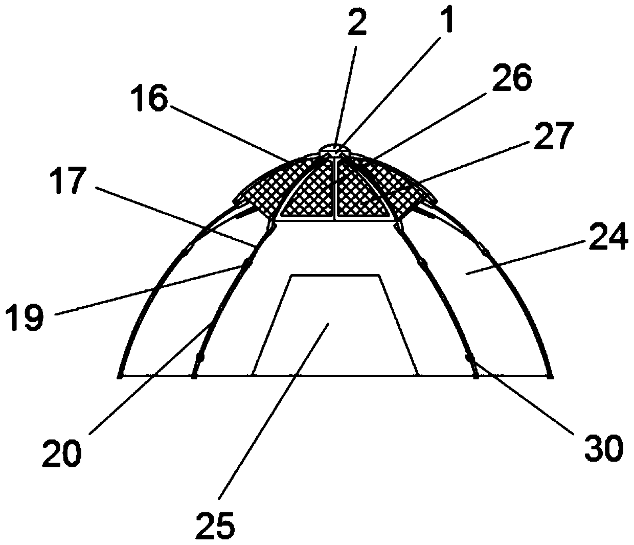
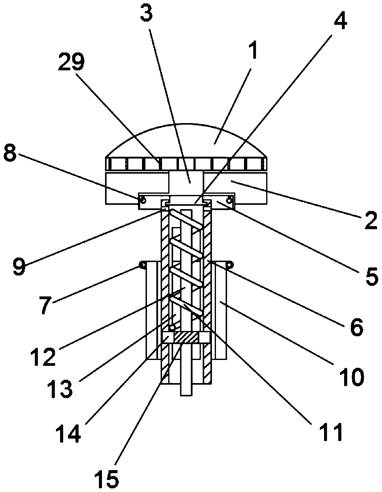
[0024] Embodiment 1: as Figure 1-6 As shown, a portable solar self-power generation tent includes a turning block 1, the outer wall of the turning block 1 is provided with anti-skid lines 29, the bottom of the turning block 1 is fixedly connected with a connecting shaft 3, and the outer side of the connecting shaft 3 The top ring 2 is movably socketed, the bottom of the coupling shaft 3 runs through the top ring 2 and is fixedly connected with a cover plate 5, the bottom of the cover plate 5 is fixedly connected with a key 4, and the bottom of the key 4 is movably engaged There is a sleeve 6, and guide grooves 13 are provided on both sides of the sleeve 6, and a bearing ring 14 is movably connected to the inner cavity of the sleeve 6, and a cable tube 12 is arranged in the bearing ring 14, and the cable The outer side of the tube 12 is wound with a spring 11, the spring 11 is located between the bearing ring 14 and the key 4, the outer side of the sleeve 6 is movably sleeved ...
Embodiment 2
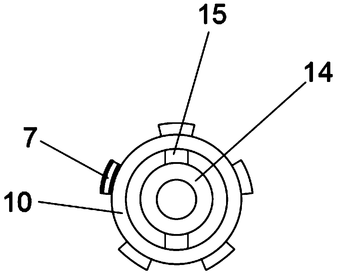
[0025] Embodiment 2: as Figure 1-7 As shown, a portable solar self-power generation tent includes a turning block 1, the outer wall of the turning block 1 is provided with anti-skid lines 29, the bottom of the turning block 1 is fixedly connected with a connecting shaft 3, and the outer side of the connecting shaft 3 The top ring 2 is movably socketed, the bottom of the coupling shaft 3 runs through the top ring 2 and is fixedly connected with a cover plate 5, the bottom of the cover plate 5 is fixedly connected with a key 4, and the bottom of the key 4 is movably engaged There is a sleeve 6, and guide grooves 13 are provided on both sides of the sleeve 6, and a bearing ring 14 is movably connected to the inner cavity of the sleeve 6, and a cable tube 12 is arranged in the bearing ring 14, and the cable The outer side of the tube 12 is wound with a spring 11, the spring 11 is located between the bearing ring 14 and the key 4, the outer side of the sleeve 6 is movably sleeved ...
PUM
 Abstract
Description
Claims
Application Information
 - R&D
- Intellectual Property
- Life Sciences
- Materials
- Tech Scout
- Unparalleled Data Quality
- Higher Quality Content
- 60% Fewer Hallucinations
Browse by: Latest US Patents, China's latest patents, Technical Efficacy Thesaurus, Application Domain, Technology Topic, Popular Technical Reports.
© 2025 PatSnap. All rights reserved.Legal|Privacy policy|Modern Slavery Act Transparency Statement|Sitemap|About US| Contact US: help@patsnap.com


