

A kind of microsensor, preparation and use method thereof
A micro-sensor and micro-groove technology, applied in the field of micro-nano sensors, can solve the problems of inability to effectively capture micron-level and sub-micron-level impurity particles in the air, inconvenient on-site analysis, and large volume.
- Summary
- Abstract
- Description
- Claims
- Application Information
AI Technical Summary
Problems solved by technology
Method used
Image

Examples
Embodiment 1
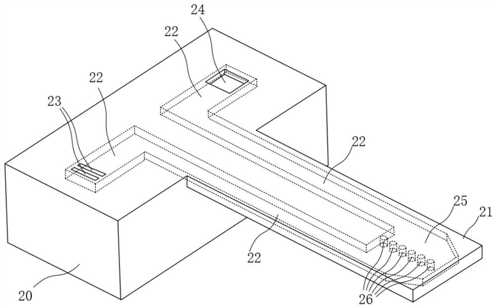
[0083] Such as figure 1 As shown, the present invention provides a microsensor, comprising:
[0084] A chip substrate 20, the chip substrate 20 includes an air inlet 23 and an air outlet 24;
[0085] A resonant micro-cantilever beam 21, the resonant micro-cantilever beam 21 extends a predetermined distance outward from the chip substrate 20, and includes a micro-channel 22 and a cavity 25 connected to the micro-channel 22 inside, the The height of the micro-channel 22 and the cavity 25 is not less than the width of the air inlet 23; connected, the cavity 25 is provided with a micro filter grating 26, the gap between the micro filter grating 26 and the inner wall of the cavity 25 is not greater than the gap between the micro filter grating 26 itself, and the micro filter grating The gap of the grid 26 itself is smaller than the width of the air inlet 23 .
[0086] As an example, the micro-grid 26 runs through the cavity 25, that is, the micro-grid 26 is in contact with the u...
Embodiment 2
[0093] Such as Figure 2-10 Shown, the present invention provides a kind of preparation method of microsensor, comprises the following steps:
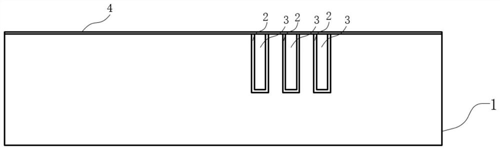
[0094] Such as figure 2 As shown, step S1 is first performed: a silicon substrate 1 is provided, and the silicon substrate 1 includes one of a single-side polished silicon substrate and a double-sided polished silicon substrate, and then prepared on the polished surface of the silicon substrate 1 Micro grating comprising micro cylinders.
[0095] Specifically, preparing the micro-grid includes the following steps:
[0096] S1-1: Etching a number of cylindrical grooves on one side of the silicon substrate 1 by ion reactive etching, the gap between adjacent cylindrical grooves ranges from 0.05 μm to 4 μm, preferably 0.1 μm to 2 μm, In this embodiment, the gap between the cylindrical grooves is set to 0.1 μm to block most PM2.5 particles.
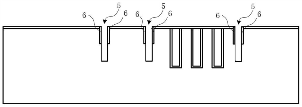
[0097] S1-2: A thermal oxidation process is used to form a protective layer 2 on the inner sur...
Embodiment 3
[0113] The present invention also provides a method for using a microsensor, comprising the following steps:
[0114] S-A: Use the phase-locked loop circuit to collect the resonant frequency of the microsensor synchronously as the baseline;
[0115] S-B: Connect the vacuum pump to the gas outlet of the microsensor, turn on the vacuum pump, and suck the gas to be measured into the microchannel from the inlet of the microsensor, and the particles within the scale selection range will be combined with the microchannel The connected micro-filter grid intercepts, causing the drop of the resonant frequency of the micro-sensor; wherein, the micro-filter grid is located in the cavity connected with the micro-channel, and the height of the micro-channel and the cavity is Not less than the width of the air inlet, the gap between the micro-grid and the inner wall of the cavity is not greater than the gap between the micro-grid itself, and the gap between the micro-grid itself is smaller ...
PUM
| Property | Measurement | Unit |
|---|---|---|
| diameter | aaaaa | aaaaa |
| height | aaaaa | aaaaa |
| thickness | aaaaa | aaaaa |
Abstract
Description
Claims
Application Information