Eureka AIR delivers breakthrough ideas for toughest innovation challenges, trusted by R&D personnel around the world.

Limiting mechanism of Hall sensor

A technology of Hall sensor and limit mechanism, which is applied in the direction of instruments, measuring devices, devices using electric/magnetic methods, etc., can solve the problems of separation of pins from the main board, unstable limit fixation, etc., and achieve easy operation, The limit is fixed and stable, and the effect is convenient to use

Inactive Publication Date: 2018-11-27
FOSHAN CHUANDONG MAGNETOELECTRICITY +1
View PDF3 Cites 1 Cited by
  • Summary
  • Abstract
  • Description
  • Claims
  • Application Information

AI Technical Summary

Problems solved by technology

[0004] The purpose of the present invention is to solve the problem that when the existing Hall sensor limit mechanism performs limit installation on the Hall sensor, the limit fixation is unstable, and the problem that the pins are easily separated from the main board is easily caused, and a Hall sensor is proposed. limit mechanism

Method used

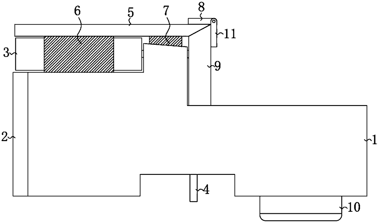
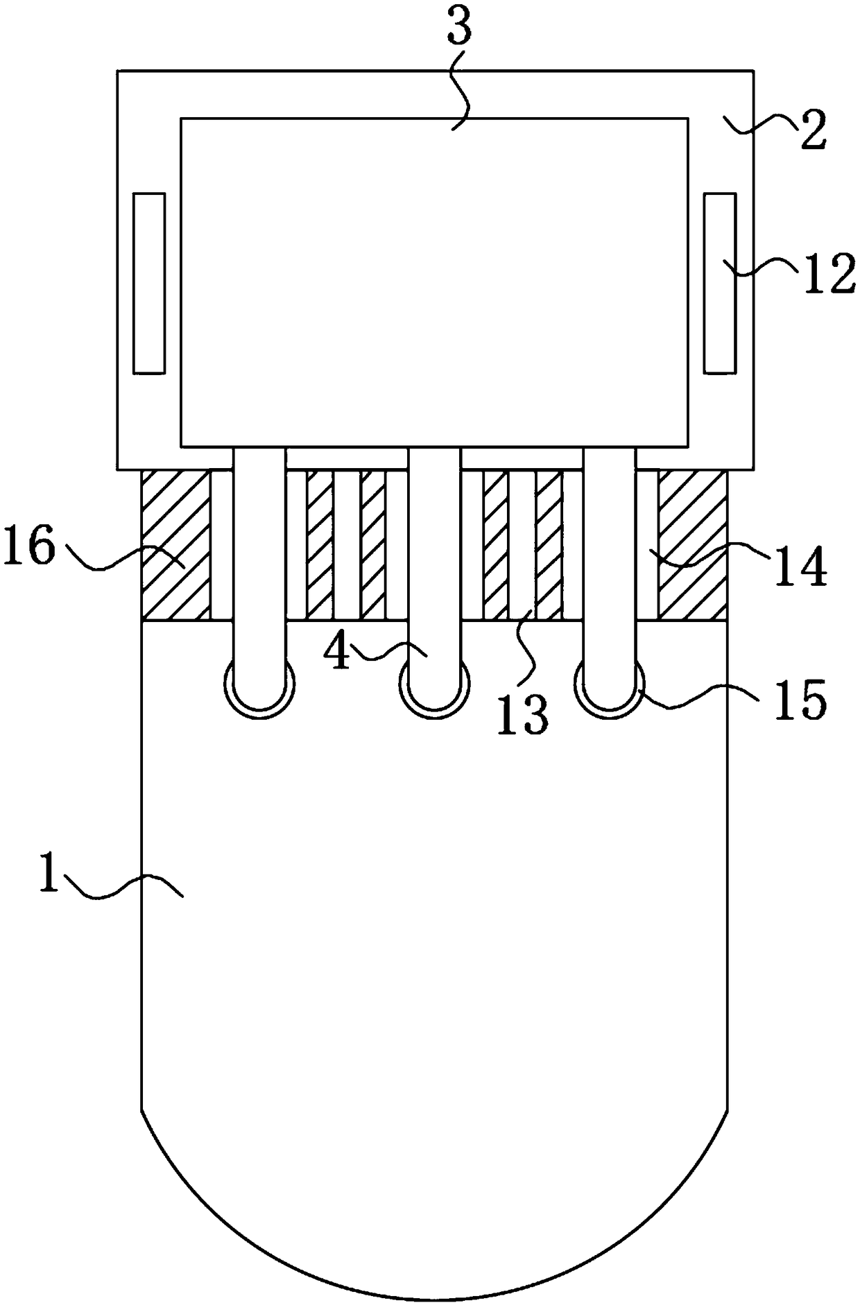
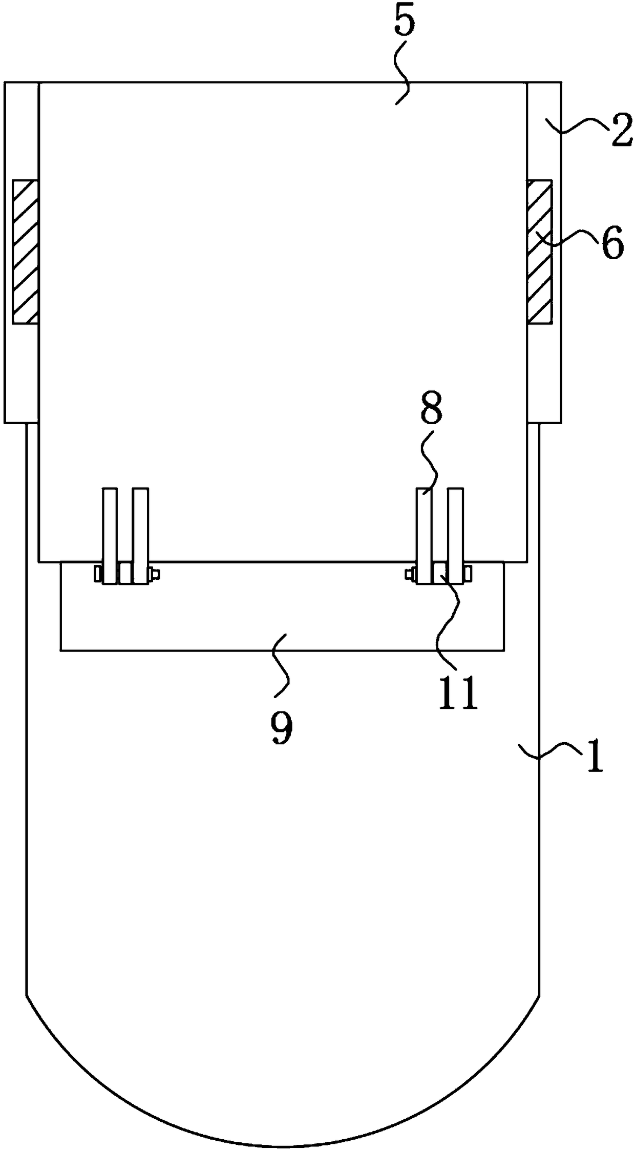

Image

  • Limiting mechanism of Hall sensor
  • Limiting mechanism of Hall sensor
  • Limiting mechanism of Hall sensor

Examples


Embodiment Construction

[0018] The following will clearly and completely describe the technical solutions in the embodiments of the present invention with reference to the accompanying drawings in the embodiments of the present invention. Obviously, the described embodiments are only some, not all, embodiments of the present invention.

[0019] refer to Figure 1-3 , a Hall sensor limit mechanism, including a main board positioning part 1 and an installation part 2, a support leg 10 is installed at the bottom of the main board positioning part 1, an installation groove is opened on the installation part 2, and a Hall sensor is glued and connected in the installation groove. The sensor 3 is provided with a plurality of pins 4 on the Hall sensor 3, and an inclined surface 16 is provided at the junction of the main board positioning part 1 and the installation part 2, and a plurality of pin positioning grooves 14 are provided on the inclined surface 16, and the main board positioning part 1 and the mount...


PUM


Abstract

The invention discloses a limiting mechanism of a Hall sensor. The limiting mechanism comprises a main board positioning portion and a mounting portion. Support legs are installed at the bottom of themain board positioning portion. A mounting slot is formed in the mounting portion. A hall sensor is arranged in the mounting slot in a bonding connection manner; and a plurality of pins are arrangedat the hall sensor. An oblique plane is arranged at a connection part between the main board positioning portion and the mounting portion; a plurality of pin positioning slots are formed in the oblique plane; through holes are formed in the main board positioning portion by corresponding to the pins; and the pins pass through the pin positioning slots and the through holes. According to the invention, with the through holes and the pin positioning slots, a hall sensor can be located and installed conveniently; the hall sensor can be limited and fixed conveniently by using a first insertion slot, a second insertion slot, a first plugging block, a second plugging block, a first baffle and a second baffle; and the first baffle and the second baffle are fixed by the oblique plane and two mounting blocks and then are installed by bolts, so that the operation becomes convenient.

Description

technical field [0001] The invention relates to the technical field of Hall sensors, in particular to a Hall sensor limiting mechanism. Background technique [0002] The Hall sensor is a magnetic field sensor made according to the Hall effect. Hall devices have many advantages, such as firm structure, small size, light weight, long life, easy installation, high precision and good linearity. The Hall sensor can be used to measure the angular velocity. Stick a piece of magnetic steel on the edge of the disc of non-magnetic material. The Hall sensor is placed close to the edge of the disc. When the disc rotates once, the Hall sensor outputs a pulse, which can be measured The number of revolutions (counter), if connected to the frequency meter, the rotational speed can be measured. [0003] At present, the main board of the parking heater controls the wind speed of the heater by installing a Hall sensor, so as to realize the purpose of heating the car when the car is parked. ...

Claims


Application Information

Patent Timeline
Patent Type & Authority Applications(China)
IPC IPC(8): G01P1/00G01P3/44
CPCG01P1/003G01P3/44
Inventor 龙克文颜天宝
Owner FOSHAN CHUANDONG MAGNETOELECTRICITY
Why Eureka
Eureka Blog
Learn More