
A Spaceborne Distributed Synthetic Aperture Microwave Radiometer System Based on Data Fusion

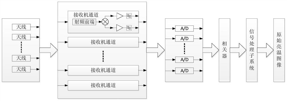
A technology of microwave radiometer and synthetic aperture, applied in radio wave measurement system, radio wave reflection/re-radiation, utilization of re-radiation, etc., can solve the problem of limited spatial resolution, complex system hardware structure and signal processing, and bulky scanning platform Problems such as system hardware structure and signal processing, to achieve the effect of improving two-dimensional spatial resolution, reducing complexity and engineering manufacturing difficulty, and engineering difficulty

Active Publication Date: 2021-04-13
XIAN INSTITUE OF SPACE RADIO TECH
View PDF2 Cites 0 Cited by
  • Summary
  • Abstract
  • Description
  • Claims
  • Application Information

AI Technical Summary

Problems solved by technology

For large synthetic aperture microwave radiometers, due to the large number of antenna units and channel units, the system hardware structure and signal processing will be very complex, and the mass increase and antenna deformation brought by large array antennas restrict the performance of synthetic aperture microwave radiometers. scale, which in turn limits its further improvement in spatial resolution
[0007] To sum up, the spaceborne microwave radiometer system of the existing system is limited by factors such as large array antenna, heavy scanning platform or complex system hardware structure and signal processing to further improve the spatial resolution.

Method used


Image

  • A Spaceborne Distributed Synthetic Aperture Microwave Radiometer System Based on Data Fusion
  • A Spaceborne Distributed Synthetic Aperture Microwave Radiometer System Based on Data Fusion
  • A Spaceborne Distributed Synthetic Aperture Microwave Radiometer System Based on Data Fusion

Examples


Embodiment

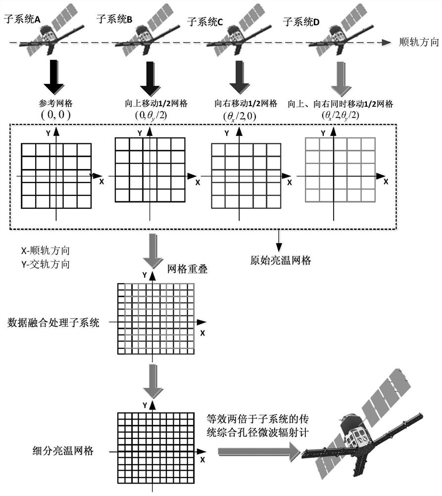
[0049] Taking the two-dimensional synthetic aperture microwave radiometer system as an example, assuming that the two-dimensional directions are X-axis (track direction) and Y-axis (cross-gauge direction), select the original grid of one of the synthetic aperture microwave radiometer subsystems as a reference . Through the preliminary research, it can be known that if the original grid is to be equally spaced in the two-dimensional direction, the number of original grid divisions is just equal to the number of required synthetic aperture microwave radiometer subsystems. Such as figure 2 As shown, an example of grid division and data fusion when N=M=2 is given. At this time, the distributed synthetic aperture microwave radiometer system consists of four identical synthetic aperture microwave radiometer subsystems, named A, B, C, and D, respectively.

[0050] Among them, A is used as the basic reference unit, and B adjusts θ in the Y-axis direction (cross-track direction) on ...


PUM


Abstract

A spaceborne distributed synthetic aperture microwave radiometer system based on data fusion, including a data fusion processing subsystem and at least N*M identical synthetic aperture microwave radiometer subsystems, N and M respectively depend on the order of the entire system The ratio of the spatial resolution in the track and cross-track directions to the spatial resolution in the along-track and cross-track directions of the synthetic aperture microwave radiometer subsystem; all the synthetic aperture microwave radiometer subsystems are arranged at the same track height, and in The projection grid on the ground has regular overlapping; each synthetic aperture microwave radiometer subsystem obtains the ground brightness temperature image and records it as the original brightness temperature image; the data fusion processing subsystem according to each synthetic aperture microwave radiometer subsystem The overlapping relationship of the original grid, the projection grid of the whole system on the ground is determined by data fusion and recorded as the brightness temperature value of the subdivided grid, that is, the high-resolution brightness temperature data after data fusion, the high-resolution brightness temperature The data has increased by N times and M times in the along-track direction and the cross-track direction, respectively.

Description

technical field [0001] The invention relates to a space-borne distributed synthetic aperture microwave radiometer system based on data fusion, which belongs to the technical field of space microwave remote sensing. Background technique [0002] The microwave radiometer system is an important payload of spaceborne passive microwave remote sensing, which can mainly obtain important global physical parameters, such as soil moisture, ocean salinity, atmospheric temperature and humidity, etc. At present, microwave radiometer systems mainly include real aperture microwave radiometer system, phased array microwave radiometer system, synthetic aperture microwave radiometer system, etc. However, because the microwave radiometer system of the existing system is limited in obtaining high-spatial-resolution passive microwave remote sensing images, further improving the spatial resolution of space-borne passive microwave remote sensing has always been an important issue in passive microw...

Claims


Application Information

Patent Timeline
Patent Type & Authority Patents(China)
IPC IPC(8): G01S13/90
CPCG01S13/90G01S3/02
Inventor 卢海梁李一楠吕容川李浩王佳坤李鹏飞宋广南杨小娇
Owner XIAN INSTITUE OF SPACE RADIO TECH
Learn More