Glasses lens cleaning device
A technology for cleaning devices and spectacle lenses, applied in the field of machinery, can solve the problems of ultrasonic damage, not suitable for ordinary people, loss, etc., and achieve the effect of compact product structure, easy to carry, and reduced volume
- Summary
- Abstract
- Description
- Claims
- Application Information
AI Technical Summary
Problems solved by technology
Method used
Image

Examples
Embodiment 1
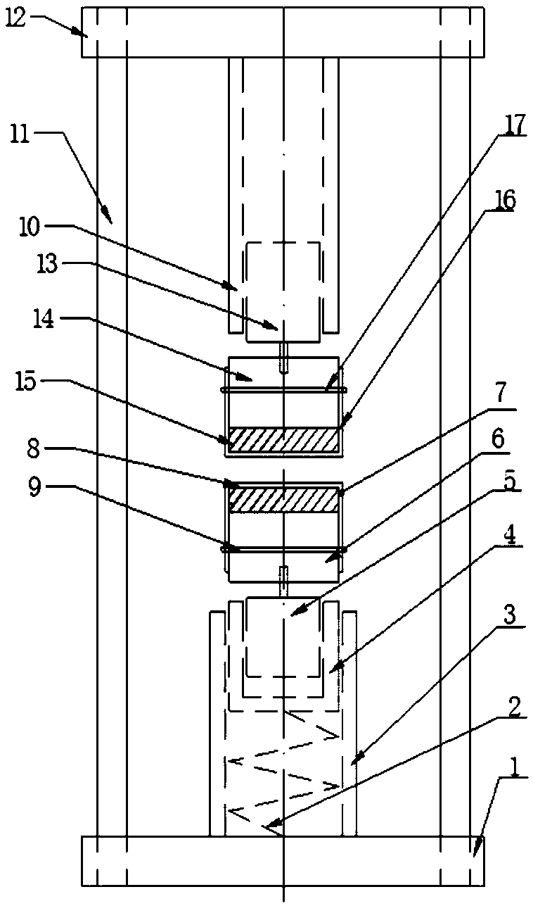
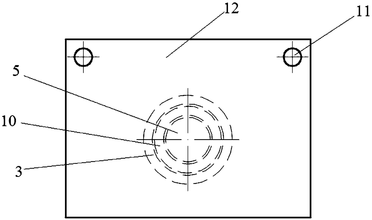
[0029] see Figure 1 to Figure 3 A spectacle lens cleaning device includes a base 1 and a support plate 12 oppositely arranged, and supports 11 are arranged at both ends of the base 1, and the upper ends of the two supports 11 are plugged and connected to the same support plate 12 by bolts, the base 1, the support 11 and support plate 12 form a frame. A first cleaning part and a second cleaning part are respectively connected to the base 1 and the support plate 12 .
[0030] The first cleaning part includes a spring 2 , a rail cover 3 , a movable block 4 , a first electric motor 5 , a first cork block 6 , a first sponge block 7 and a first spectacle cloth 8 . The guide rail cover 3 is fixed on the base 1 by bolts, the inner wall of the guide rail cover 3 is slidingly connected with the movable block 4, the inner side of the guide rail cover 3 is provided with a spring 2, the lower end of the spring 2 is fixedly connected with the base 1 by welding, and the upper end is fixed ...
Embodiment 2
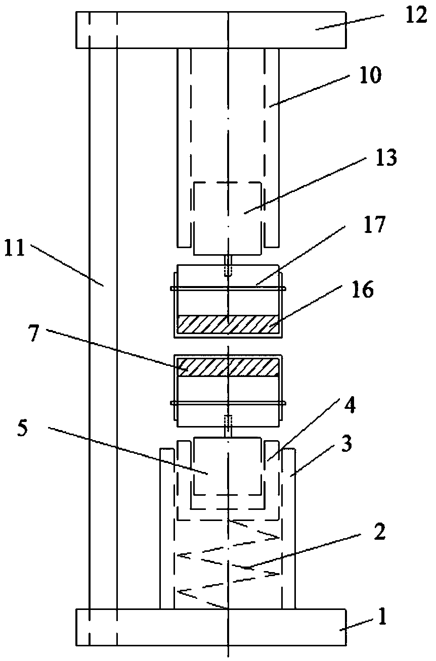
[0041] refer to Figure 4The difference between this embodiment and Embodiment 1 is that it also includes an upper casing 18 and a lower casing 19, the upper end of the upper casing 18 is fixedly connected with the support plate 12 by bolts, and the fixing sleeve 10 is arranged in the upper casing 18 , the lower end surface of the upper shell 18 is located between the lower end surface and the upper end surface of the second sponge block 15; the lower end of the lower shell 19 is fixedly connected with the base 1 by bolts, and the guide rail cover 3 is arranged in the lower shell 19, and the working state Next, the upper end surface of the lower housing 19 is located between the lower end surface and the upper end surface of the first cork block 6; the two housings protect the electric motor, the spring 2, the movable block 4 and the guide rail cover 3, and improve the service life .
Embodiment 3
[0043] refer to Figure 5 , The difference between this embodiment and Embodiment 1 is that the frame composed of the base 1 , the bracket 11 and the support plate 12 is replaced by the shell 20 . The rail cover 3 is fixed on the inner side of the bottom surface of the housing 20 , and the fixing sleeve 10 is fixed on the inner side of the top surface of the housing 20 . The housing 20 is provided with a door panel, and the door panel is connected with the housing 20 through a lock. Other components are located in the housing 20 to ensure the cleanliness of the first and second spectacle cloths.
PUM
 Abstract
Description
Claims
Application Information