Electric hair dryer

The technology of a hair dryer and a hair dryer, which is applied to clothing, hairdressing equipment, hair drying devices, etc., can solve the problems such as the inability to further increase the wind speed, the inability to install large fan blades, and the laborious use, so as to improve the drying efficiency, speed, and efficiency. Fast drying effect

Pending Publication Date: 2018-11-30
KINGCLEAN ELECTRIC
View PDF9 Cites 5 Cited by
  • Summary
  • Abstract
  • Description
  • Claims
  • Application Information

AI Technical Summary

Problems solved by technology

[0003] The motor of the existing hair dryer is mostly installed in the hair dryer, and there is a certain distance between the handle and the motor. When the motor is working, it will vibrate and generate torque at the handle. The grip is not good, and it is more laborious to use.
Some hair dryers set the motor in the handle, but due to the limitation of the handle diameter and unreasonable structure, it is impossible to install large fan blades, resulting in the wind speed cannot be further increased

Method used


Image

  • Electric hair dryer
  • Electric hair dryer
  • Electric hair dryer

Examples


Embodiment 1

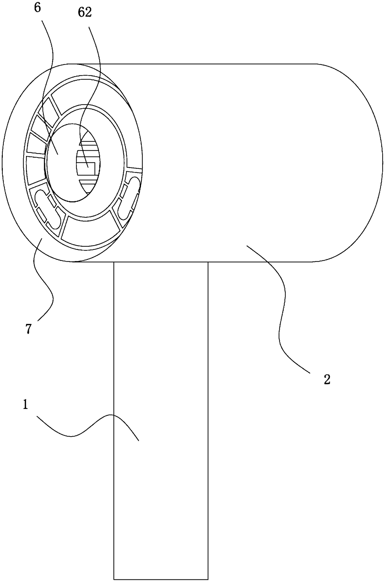
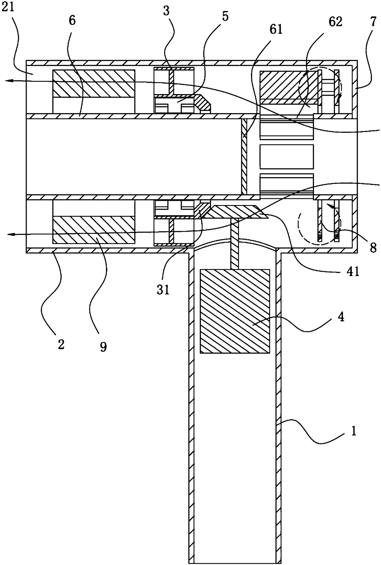
[0026] This embodiment discloses an electric hair dryer. like figure 1 As shown, the hair dryer includes a handle 1 and a blower 2 which are connected internally, and an inner cavity pipe 6 is sleeved on the inner side of the blower 2, and the end of the air inlet side of the blower 2 and the air inlet section of the inner cavity pipe 6 are An annular tailgate 7 is connected between the ends. An air inlet 62 is provided on the side wall of the inner tube 6 close to the air inlet, and the air flow passes through the air inlet of the inner tube 6 and the air inlet 62 successively and then enters the hair dryer.

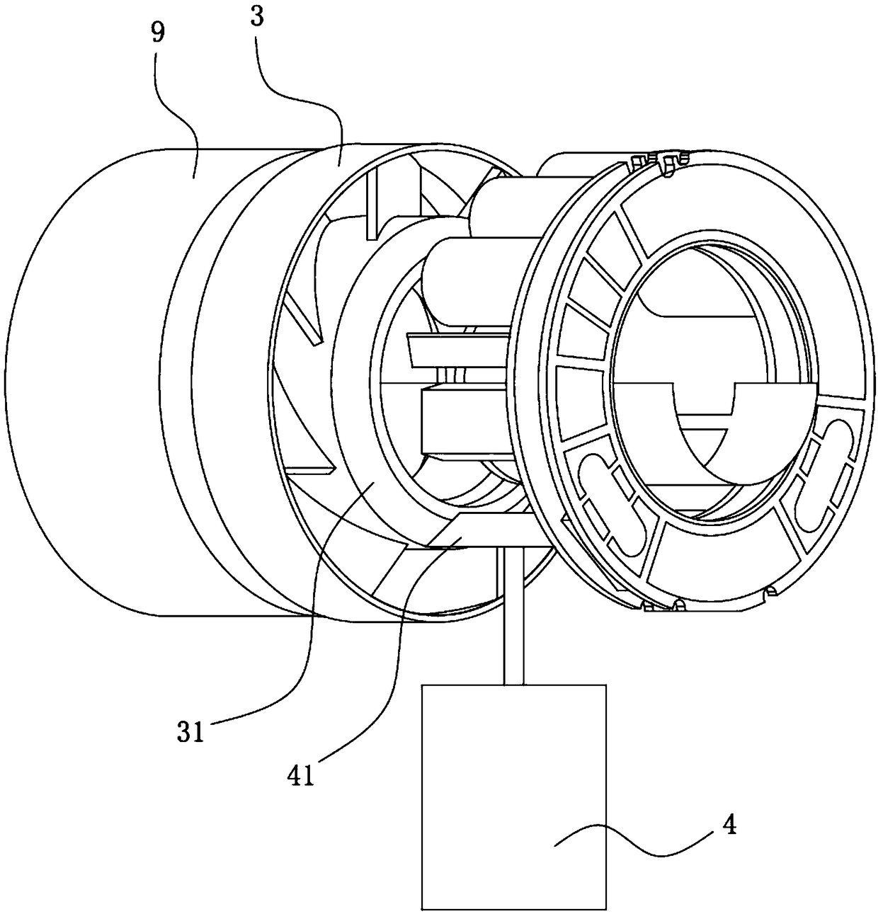
[0027] like figure 2 and image 3 As shown, fan blades 3 and heating wires 9 are sequentially arranged in the fan cylinder 2 along the blowing direction, the fan blades 3 are ring-shaped fan blades with bearings 5 ​​pierced in the middle, and the inner cavity tube 6 is pierced in the middle of the bearings 5; the handle 1 is provided with a motor 4 . The output en...

Embodiment 2

[0036] This embodiment discloses an electric hair dryer, the structure of which is basically the same as that of Embodiment 1. The difference is that: if Figure 5 As shown, a worm 45 is provided at the output end of the motor 4, and a worm wheel 35 meshing with the worm 45 is provided on the fan blade 3, and the axis of the worm is perpendicular to or forms a certain angle with the axis of the worm wheel. The motor 4 drives the worm 45 to rotate around the vertical axis, and the worm 45 drives the worm wheel 35 to rotate around the horizontal axis, so as to achieve the same motion effect of driving the fan blade 3 as in the first embodiment.

[0037] The tooth of worm gear 35 can be arranged on the outer wall of fan blade 3 (as Figure 5 a) or on the side wall (such as Figure 5 As shown in b), it does not affect the engagement with the worm, and only needs to change the installation position of the worm 45 accordingly.

Embodiment 3

[0039] This embodiment discloses an electric hair dryer, the structure of which is basically the same as that of Embodiment 1. The difference is that: the direction conversion part includes a motor universal joint and a fan blade universal joint connected by an inclined cross connector, the motor universal joint is arranged at the output end of the motor, and the fan blade universal joint is arranged at the fan blade on the axis of rotation.

[0040] The output end of the motor rotates around the vertical line, and then drives the motor universal joint to rotate in the same direction; the motor universal joint drives the fan blade universal joint to rotate around the horizontal line or an axis close to the horizontal direction through the cross connector, and then drives the fan blade around the horizontal line Or an axis close to the horizontal direction can be rotated, so as to achieve the same motion effect of driving the fan blade to rotate as in the first embodiment.


PUM


Abstract

The present invention discloses an electric hair dryer, belongs to the technical field of hair drying devices, and is designed for solving the problems that an existing electric hair dryer is low in air speed and the holding feel is poor. The electric hair dryer comprises a handle and an air duct which are communicated with each other, a fan blade is disposed in the air duct, and a motor is disposed in the handle; an output shaft of the motor and a rotating shaft of the fan blade are arranged with an included angle, and the output shaft of the motor is in transmission connection with the fan blade via a direction transformation part. The motor of the electric hair dryer does not generate a moment at the handle, the holding feel is improved, and labor is saved when the electric hair dryer is used; the blowing speed of the fan blade is fast and the air quantity is large, the drying efficiency of the electric hair dryer is improved, and the range of application of the electric hair dryeris widened.

Description

technical field [0001] The invention relates to the technical field of hair dryers, in particular to an electric hair dryer with a motor arranged in a handle. Background technique [0002] A hair dryer is a commonly used household appliance, which uses a motor to drive the fan blades to rotate to blow out hot air for drying wet objects such as hair. [0003] Most of the motors of existing hair dryers are installed in the hair dryer, and there is a certain distance between them and the handle. When the motor is working, it will vibrate and generate torque at the handle. The grip is not good, and it is difficult to use. Some hair dryers set the motor in the handle, but due to the limitation of the diameter of the handle and the unreasonable structure, it is impossible to install large fan blades, so the wind speed cannot be further increased. Contents of the invention [0004] The purpose of the present invention is to provide a hair dryer with good grip and high wind speed...

Claims


Application Information

Patent Timeline
Patent Type & Authority Applications(China)
IPC IPC(8): A45D20/12
CPCA45D20/12
Inventor 倪祖根
Owner KINGCLEAN ELECTRIC
Why Eureka
Try Eureka