
Negative pressure vacuum system for filtering solid particles and liquid

A vacuum system and solid particle technology, which is applied in the direction of dispersed particle filtration, transportation and packaging, and dispersed particle separation, can solve problems such as accelerating equipment, wear, and affecting vacuum degree, so as to improve service life, reduce use cost, and improve production efficiency effect

Pending Publication Date: 2018-11-30
苏州沧海真空机械有限公司
View PDF0 Cites 1 Cited by
  • Summary
  • Abstract
  • Description
  • Claims
  • Application Information

AI Technical Summary

Problems solved by technology

[0002] At present, the negative pressure vacuum system is widely used in machinery, chemical industry, medicine, food, electronics, metallurgy, petroleum and other fields, but the existing negative pressure vacuum system has poor stability, high failure rate, and needs frequent shutdown for maintenance, which affects production efficiency
One of the main reasons for maintenance is that the vacuumed container contains a considerable amount of impurities, mainly solid particles and liquid impurities. After these impurities enter the vacuum pump, the particles will accelerate the wear of the equipment, cause the seal to fail, and affect the vacuum degree, while the liquid The moisture in the vacuum will cause the equipment to rust and affect the service life of the equipment. Therefore, in order to ensure the comprehensive performance of the vacuum pump, the solid particles and liquid impurities in the circuit must be removed in time in actual use.
However, many companies now use complex and expensive multi-media filters, which are not only costly, but also very inconvenient to maintain.

Method used


Image

  • Negative pressure vacuum system for filtering solid particles and liquid
  • Negative pressure vacuum system for filtering solid particles and liquid

Examples


Embodiment Construction

[0013] The applicant will describe in detail the specific implementation of the present invention below in conjunction with the accompanying drawings, but the applicant's description of the embodiments is not a limitation to the technical solution, and any changes made in form but not in substance according to the concept of the present invention should be regarded as the present invention. scope of protection.

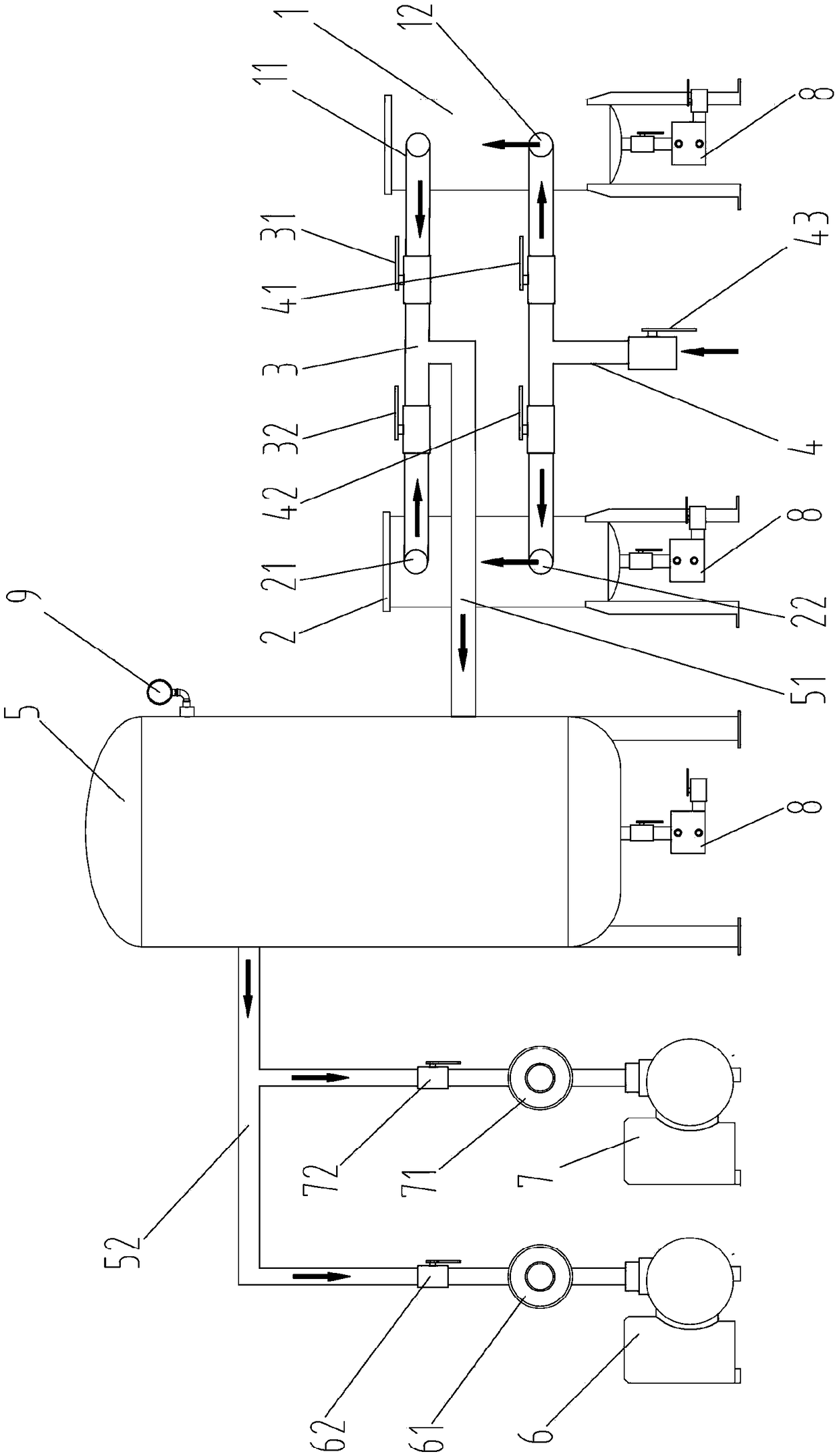
[0014] see figure 1 , the present invention relates to a negative pressure vacuum system for filtering solid particles and liquids, comprising a first coarse dust filter tank 1, a second coarse dust filter tank 2, a first three-way pipe 3, a second three-way pipe 4, A vacuum tank 5 , a first vacuum pump 6 and a second vacuum pump 7 . The vacuum tank 5 leads an air inlet pipe 51 and an air outlet pipe 52 from the tank cavity, and a vacuum gauge 9 is arranged on the side wall of the vacuum tank 5 at the top. The first interface of the first three-way pipe 3 communicat...


PUM


Abstract

A negative pressure vacuum system for filtering solid particles and a liquid comprises a first dust coarse filtration tank, a second dust coarse filtration tank, a first tee, a second tee, a vacuum tank, a first vacuum pump and a second vacuum pump, a gas inlet pipeline and a gas outlet pipeline are led out from the tank chamber of the vacuum tank, the first port of the first tee is communicated with the first gas outlet of the first dust coarse filtration tank, the second port of the first tee is communicated with the second gas outlet of the second dust coarse filtration tank, the third portof the first tee is communicated with the gas inlet pipeline of the vacuum tank, the first port of the second tee is communicated with the first gas inlet of the first dust coarse filtration tank, the second port of the second dust coarse filtration tank is communicated with the second gas inlet of the second dust coarse filtration tank, the third port of the second tee is externally connected with a user's vacuum use port, the pump ports of the first vacuum pump and the second vacuum pump are communicated with the gas outlet pipeline of the vacuum tank, the first vacuum pump is connected with the first vacuum filter and a first vacuum pump valve, and the second vacuum pump is connected with the second vacuum filter and a second vacuum pump valve. The system has the advantages of convenience in pipeline control, effectiveness in filtering dust particles, prolongation of the life of filter elements, improved system stability, high production efficiency and low cost.

Description

technical field [0001] The invention belongs to the technical field of filtering devices, and in particular relates to a negative pressure vacuum system for filtering solid particles and liquids. Background technique [0002] At present, the negative pressure vacuum system is widely used in machinery, chemical industry, medicine, food, electronics, metallurgy, petroleum and other fields, but the existing negative pressure vacuum system has poor stability, high failure rate, and needs frequent shutdown for maintenance, which affects production efficiency. One of the main reasons for maintenance is that the vacuumed container contains a considerable amount of impurities, mainly solid particles and liquid impurities. After these impurities enter the vacuum pump, the particles will accelerate the wear of the equipment, cause the seal to fail, and affect the vacuum degree, while the liquid The moisture in the vacuum will cause the equipment to rust and affect the service life of...

Claims


Application Information

Patent Timeline
IPC IPC(8): B01D46/00
CPCB01D46/90B01D46/58
Inventor 高峰
Owner 苏州沧海真空机械有限公司
Learn More