Fixing mould clamp

A fixture and mold technology, applied in the field of fixtures, can solve the problems of limited use range, waste of time and manpower, and low practicability, and achieve the effects of wide use range, time and cost saving, and convenient grinding

Inactive Publication Date: 2018-11-30
廖像达
0 Cites 4 Cited by

AI-Extracted Technical Summary

Problems solved by technology

[0002] The mold fixture is a device used to clamp and fix the mold. The usual fixture needs a matching fixture to fix it, so as to realize the effect of fixing the mold, so that the scope of use of t...

Abstract

The invention provides a fixing mould clamp, and relates to the field of clamps. The fixing mould clamp comprises a base. Two sides of the top of the base are fixedly connected with a bracket. The center part of the top of the base is fixedly connected with a placing table. A cavity of the bracket is in through connection with a threaded rod. One end, adjacent to the placing table, of the threadedrod is fixedly connected with a bearing. One side, adjacent to the placing table, of the bearing is fixedly connected with a clamping plate. The center part of the left side of the clamping plate isprovided with a hole. The inner side of the hole is moveably connected with a disk through the bearing. The fixing mould clamp is capable of, through cooperation of the threaded rod, the bearing, theclamping plate, a first telescopic spring, a top plate, a digging rope, a sliding chute, a slider, a telescopic rod, a support plate, a compression spring, an iron ring, a poking rod, a second telescopic spring and a fixing rod, achieving the more stable effect in a using process of the clamp, and enabling a using range of the clamp to be wider at the same time.

Application Domain

Technology Topic

Image

  • Fixing mould clamp
  • Fixing mould clamp
  • Fixing mould clamp

Examples

  • Experimental program(1)

Example Embodiment

[0019] The technical solutions in the embodiments of the present invention will be clearly and completely described below with reference to the accompanying drawings in the embodiments of the present invention. Obviously, the described embodiments are only a part of the embodiments of the present invention, but not all of the embodiments. Based on the embodiments of the present invention, all other embodiments obtained by those of ordinary skill in the art without creative efforts shall fall within the protection scope of the present invention.
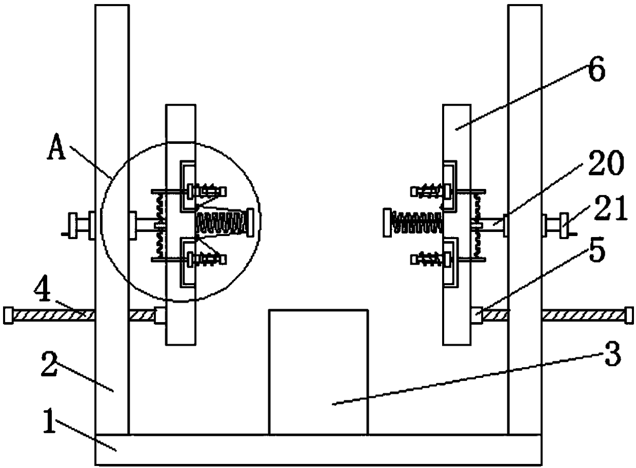
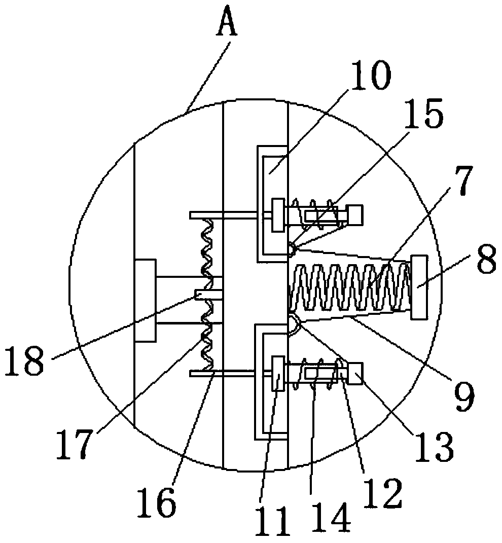
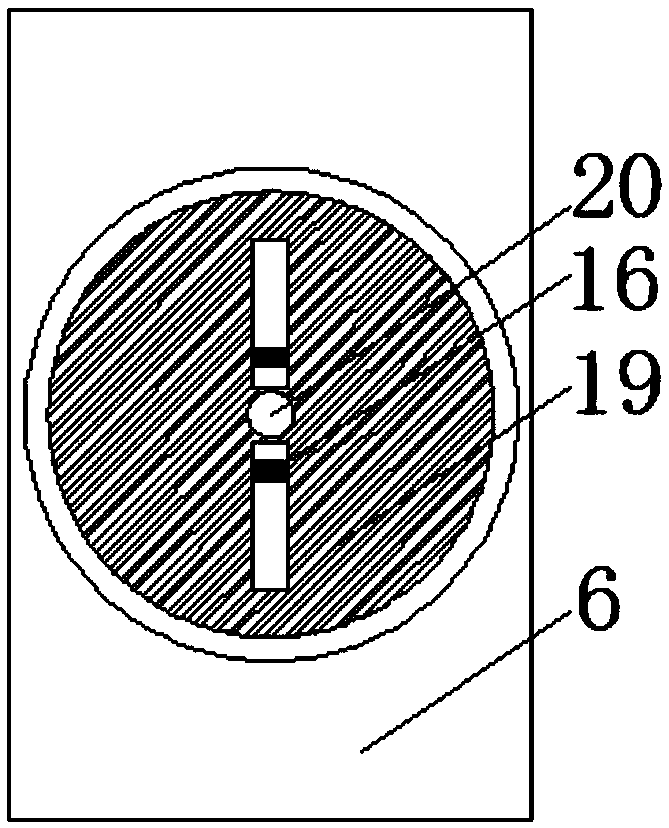
[0020] like Figure 1-3 As shown, the embodiment of the present invention provides: a fixed mold fixture, including a base 1, a bracket 2 is fixedly connected to both sides of the top of the base 1, a placing table 3 is fixedly connected to the central part of the top of the base 1, and the placing table is The top of 3 is fixedly connected with a sponge pad 23. The sponge pad 23 can play a buffering role when the mold falls, so that it does not need to be manually removed after grinding, which is convenient for the staff and can also be well protected. In the mold, the inner cavity of the bracket 2 is connected with a threaded rod 4, and the threaded rod 4 is fixedly connected with a bearing 5 at one end of the placing table 3. The side of the bearing 5 close to the placing table 3 is fixedly connected with a splint 6, and the threaded rod 4 is far away from One end of the bracket is fixedly connected with a handle 22, which is convenient for the staff to turn the rod 20, and also achieves the effect of saving labor. 6. Move closer to the placing table 3, and at the same time, the rotating rod 20 can be used to move with the splint 6, so as to rotate the disc 19, so that the mold is rotated and adjusted to achieve a more comprehensive grinding of the mold. The central part of the left side of the splint 6 is opened. There is a hole, the inner side of the hole is movably connected with a disk 19, the side of the disk 19 close to the placing table 3 is fixedly connected with a first telescopic spring 7, and the first telescopic spring 7 is fixed on the side away from the disk 19. The top plate 8 is connected. The center of the top plate 8 close to the side of the disk 19 is fixedly connected to the pull rope 9. The side of the disk 19 close to the placing table 3 is provided with two chutes 10. The two chutes 10 are located in the first telescopic spring. 7, the inner wall of the chute 10 is slidably connected with the slider 11, the right side of the slider 11 is fixedly connected with a telescopic rod 12, the end of the telescopic rod 12 away from the slider 11 is fixedly connected with a support plate 13, and the outer wall of the telescopic rod 12 is fixedly connected with a support plate 13. A compression spring 14 is sleeved, the end of the compression spring 14 away from the disc 19 is fixedly connected to the side of the support plate 13 close to the disc 19, and the pull rope 9 is away from the top plate 8 and passes through the disc 19 and is fixedly connected to the side of the table. The iron ring 15 is fixedly connected to the side of the support plate 13 close to the telescopic rod 12, the side of the slider 11 away from the telescopic rod 12 is fixedly connected with a toggle rod 16, and the chute 10 on the right side of the disc 19 is provided with a toggle rod 16. The rod 16 is matched with the strip hole, the left chute 10 of the disc 19 is provided with a strip hole matching the telescopic rod 12, and the opening diameter of the chute 10 is smaller than the width of the slider, so that the slider 11 is fixed in the The inside of the chute 10 in the disc 19 prevents the slider 11 from tilting due to the gravity of the telescopic rod 12 and the support plate 13, and better completes the function of fixing the mold. The end of the toggle rod 16 away from the slider 11 penetrates through The disc 19 extends to the outside of the disc 19, the bottom of the toggle lever 16 is fixedly connected with a second telescopic spring 17, and the elastic force of the first telescopic spring 7 is greater than the elastic force of the compression spring 14, so that when the first telescopic spring is compressed , the reset force can still be maintained, and the fixation of the mold in the horizontal direction is maintained. The elastic force of the first telescopic spring 7 is greater than that of the second telescopic spring 17, so that in the case of stopping work, the tension of the first telescopic spring 7 makes the pull rope 9 Tilt and pull the support plate 13 from And the slider 11 is compressed to the second telescopic spring 17, so that the telescopic rod 12 is close to the first telescopic spring 7, and the end of the second telescopic spring 17 away from the toggle rod 16 is fixedly connected with a fixed rod 18, and the right side of the fixed rod 18 is connected to the The left side of the disk 19 is fixedly connected, the center of the disk 19 close to the side of the bracket 2 is fixedly connected with a rotating rod 20, the inner cavity of the support 2 is movably connected with a rotating rod 20, and the end of the rotating rod 20 away from the disk 19 is fixed A rotating handle 21 is connected, and one-third of the diameter of the disc 19 is the diameter of the rotating handle 21, so that it is more labor-saving for the staff to rotate the rotating rod 20, which makes the staff more convenient. During the use of the present invention, the threaded rod 4, the bearing 5. The splint 6, the first telescopic spring 7, the top plate 8, the pull rope 9, the chute 10, the slider 11, the telescopic rod 12, the support plate 13, the compression spring 14, the iron ring 15, the toggle rod 16, the second telescopic The cooperation of the spring 17 and the fixing rod 18 can achieve a more stable effect during the clamp process, and at the same time, the clamp can be used in a wider range. The purpose of rotating the grinding tool is to facilitate the grinding tool to grind the mold, which saves time and cost.
[0021] Although embodiments of the present invention have been shown and described, it will be understood by those skilled in the art that various changes, modifications, and substitutions can be made in these embodiments without departing from the principle and spirit of the invention and modifications, the scope of the present invention is defined by the appended claims and their equivalents.

PUM

no PUM

Description & Claims & Application Information

We can also present the details of the Description, Claims and Application information to help users get a comprehensive understanding of the technical details of the patent, such as background art, summary of invention, brief description of drawings, description of embodiments, and other original content. On the other hand, users can also determine the specific scope of protection of the technology through the list of claims; as well as understand the changes in the life cycle of the technology with the presentation of the patent timeline. Login to view more.

Similar technology patents

Dust collector

ActiveCN101797135AWide range of useSuction handlesEngineeringExpansion joint
Owner:SUZHOU PUWODA INTELLIGENT TECH CO LTD

Gear anti-rusting oil coating equipment

Owner:苏州济和精密传动系统有限公司

Classification and recommendation of technical efficacy words

  • Wide range of use
  • Easy to polish
Why Eureka
Try Eureka