Automatic end executing device of robot and assembly robot
A technology of end effectors and robots, which is applied in the direction of manipulators, metal processing equipment, chucks, etc., can solve the problems of cumbersome switching fixtures and cannot be assembled automatically, and achieve the effect of improving production efficiency and avoiding stagnant adjustments
- Summary
- Abstract
- Description
- Claims
- Application Information
AI Technical Summary
Problems solved by technology
Method used
Image
Examples
Embodiment 1
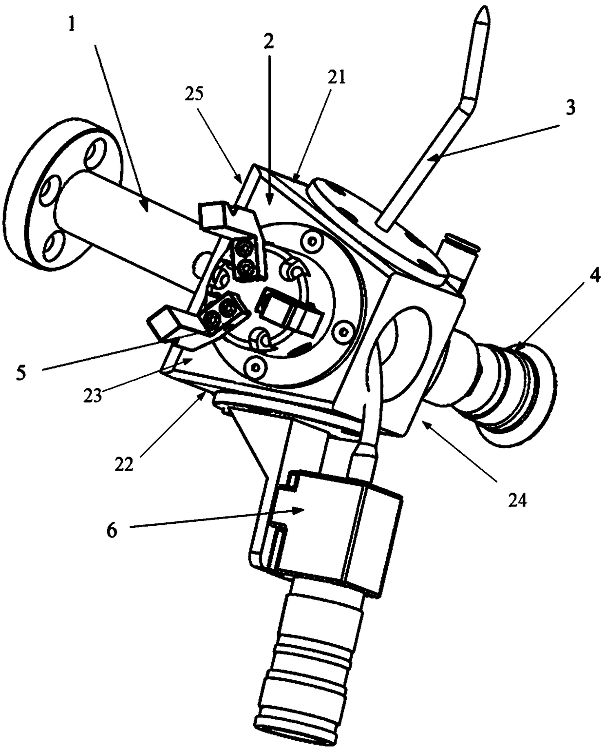
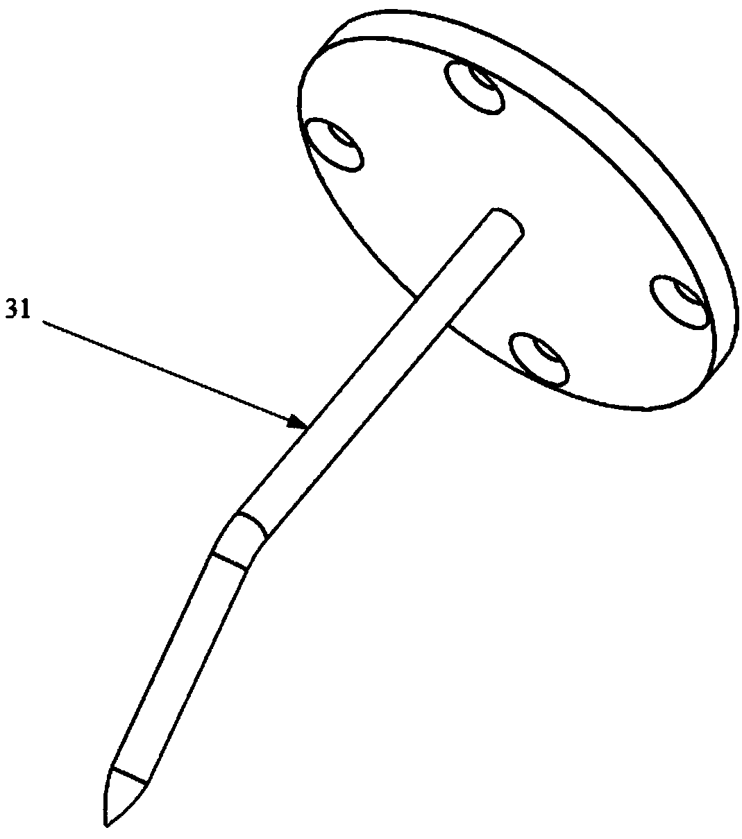
[0048] see figure 1 , the present embodiment provides an automatic end effector of a robot, comprising: a base 2; a calibration device 3 disposed on the first side of the base 2, used for calibrating the tool coordinate system of the automatic end effector, so as to improve the automatic end effector The trajectory accuracy of the device; the camera unit 6 located on the second side of the base 2 for acquiring images of the assembled components; the first assembly unit located on the third side of the base 2 for performing the first assembly operation; and The second assembly unit on the fourth side of the base 2 is used to perform a second assembly operation; wherein the assembly components include a first type assembly component and a second type assembly component; in response to the camera unit 6 acquiring the first type assembly component , the first assembly unit performs the first assembly operation; in response to the camera unit 6 capturing the image of the second typ...
Embodiment 2
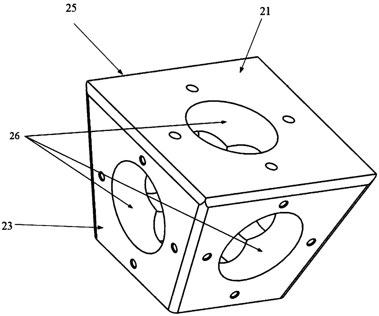
[0053] This embodiment provides an automatic end effector based on the robot of Embodiment 1. The side of the base 2 is a plane or a curved surface, and the plane is inclined relative to the bottom surface of the base. see figure 2 , what this embodiment adopts is the plane side, and the first side 21, the second side 22, the third side 23, the fourth side 24 are all inclined at a certain angle with the bottom surface 25 of the base, and the inclination of each side and the bottom surface 25 The angles are adjusted according to the actual functional units attached to each side. If the side surface of this embodiment is a curved surface, each functional unit can be adjusted on the side surface of the curved surface according to the use angle, so as to realize inclined setting. In this embodiment, through the inclined design of the side, when the robot uses the automatic end effector of this embodiment to assemble the product, due to the inclination according to the units with...
Embodiment 3
[0062] This embodiment provides an assembly robot based on Embodiment 2, which adopts the automatic end effector as required by any one of Embodiment 2.
[0063] The assembly robot of this embodiment uses the automatic end effector to realize flexible assembly of accessories in various directions through flexible rotation of the robot. The automatic end effector of the assembly robot identifies the information of the assembly parts, coordinates the end effector, and transmits the identified information to the control unit of the robot. The control unit determines the matching of the automatic end effector for the robot. Fixtures perform assembly tasks, thereby realizing the automation of product assembly. The robot uses the automatic end effector to determine the parts to be assembled according to the control unit, the robot identifies all the parts, and selects the required parts for assembly.
[0064] The assembly robot of this embodiment adopts the automatic end effector t...
PUM
 Abstract
Description
Claims
Application Information
 - R&D
- Intellectual Property
- Life Sciences
- Materials
- Tech Scout
- Unparalleled Data Quality
- Higher Quality Content
- 60% Fewer Hallucinations
Browse by: Latest US Patents, China's latest patents, Technical Efficacy Thesaurus, Application Domain, Technology Topic, Popular Technical Reports.
© 2025 PatSnap. All rights reserved.Legal|Privacy policy|Modern Slavery Act Transparency Statement|Sitemap|About US| Contact US: help@patsnap.com


