A car rear spring seat installation structure

A technology of rear spring seat and installation structure, applied in elastic suspension, vehicle parts, transportation and packaging, etc., can solve the problems that the load can only be digested by itself, the service life is reduced, and the strength in the Y direction is not improved.

Active Publication Date: 2021-07-30
CHERY AUTOMOBILE CO LTD
View PDF5 Cites 0 Cited by
  • Summary
  • Abstract
  • Description
  • Claims
  • Application Information

AI Technical Summary

Problems solved by technology

Although the above-mentioned structure of the rear suspension spring installation point of the automobile has improved the strength of the spring seat to a certain extent, it still has certain defects in terms of the force transmission path and the adaptability of the vehicle model, as follows: 1. The above-mentioned spring seat will The load received is directly transmitted to the longitudinal beam, so that the X direction can be effectively supported, but the strength in the Y direction has not been improved, that is, the load in the Y direction can only be digested by itself, which reduces the service life
2. Due to different car models, the installation height of the spring seat will also change somewhat, but the spring seat installation structure in the above patent does not take this into consideration, so it can only be designed for a single car model. The spring seat installation structure poor versatility

Method used


Image

  • A car rear spring seat installation structure
  • A car rear spring seat installation structure
  • A car rear spring seat installation structure

Examples


Embodiment 1

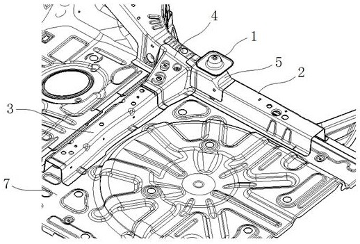
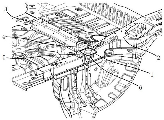
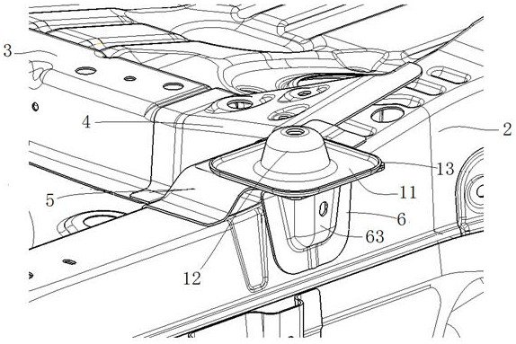
[0021] Such as figure 1 , 2 As shown, the present embodiment proposes a rear spring seat installation structure of an automobile, which specifically includes a spring seat 1, a rear longitudinal beam 2, a rear beam 3, a transverse beam connecting plate 4, a first bracket 5 and a second bracket 6, wherein : the rear longitudinal beam 2 and the rear cross beam 3 are all fixed on the rear floor 7 of the automobile, and the rear longitudinal beam 2 and the rear cross beam 3 are vertically arranged. The cross-section of the longitudinal beam connecting plate 4 is roughly in an inverted U shape, and the outer end of the transverse and longitudinal beam connecting plate 4 is provided with a continuous flange 41, and the flange 41 is fixedly connected with the rear longitudinal beam 2 by welding. The inner end of the beam connection plate 4 is sleeved on the rear cross beam 3 and welded and fixed with the rear cross beam 3; both sides of the cross and longitudinal beam connection pla...


PUM


Abstract

The purpose of the invention is to propose a rear spring seat installation structure of an automobile with high strength and good versatility. The automobile rear spring seat installation structure of the present invention comprises a rear longitudinal beam, a spring seat, a second bracket and a first bracket, and is characterized in that the first bracket is composed of a bridge plate and a side connecting plate integrally, and the bridge plate The two ends are respectively fixedly connected to the top surface of the rear longitudinal beam, the middle top surface of the bridge plate is fixedly connected to the bottom surface of the spring seat, and the side connecting plate is fixedly connected to the inner surface of the rear longitudinal beam; the second bracket is made of The structure of the L-shaped cross-section formed by the top plate and the side plate, the side plate is fixedly connected with the outer surface of the rear longitudinal beam, and the top plate is fixedly connected with the bottom surface of the middle part of the bridge plate; the bridge plate, the side connecting plate, the side plate, the rear A cavity structure is formed between the stringers. The automobile rear spring seat installation structure of the invention is simple and convenient to install, can greatly improve the load bearing strength, meet the strength performance requirements, and adapt to the installation requirements of different vehicle models, thereby improving the versatility.

Description

technical field [0001] The invention relates to the field of automobile body structures, in particular to an automobile rear spring seat installation structure. Background technique [0002] The car will produce a certain dynamic vibration during operation. The faster the speed of the car, the greater the vibration. People generally install shock absorbing springs on the car to absorb this vibration, so that the car maintains a dynamic balance during operation. Not only that, the shock absorbing spring can also quickly absorb the shock generated when the car is bumping, so that the vehicle can return to the normal driving state, improving the comfort of the vehicle or improving the operability. [0003] The invention patent with the patent application number 201610440850.2 discloses a structure of the installation point of the rear suspension spring of an automobile, including the rear suspension spring seat installation plate, the support plate and the rear floor side longi...

Claims


Application Information

Patent Timeline
Patent Type & Authority Patents(China)
IPC IPC(8): B60G11/00
CPCB60G11/00
Inventor 何文强仰荣德陆圣梅
Owner CHERY AUTOMOBILE CO LTD
Why Eureka
Try Eureka